Onboarding Payload
The purpose of this section is to define the contents of the Onboarding Payload needed to allow onboarding a device into a Matter network. It also specifies the representation and encoding of said payload as a QR Code, as a manually entered code, and as content in an NFC tag.
Onboarding Payload Contents
The Onboarding Payload is composed of required and optional information which will be used by the Commissioner to ensure interoperability between commissioners and devices and provide a consistent user experience. Some or all of this content will be encoded into different formats, some human-readable (such as numeric string) and machine-readable (such as QR code and NFC) formats for printing or display on or integration into the device. The following are the elements that may be used in an Onboarding Payload for a Matter device.
Version
A version indication provides versioning of the payload and SHALL be included. Version for machine-readable formats is 3 bits with an initial version of 0b000. Version for Manual Pairing Code is 1 bit with an initial version of 0b0.
Rationale: This allows a way to introduce changes to the payload as needed going into the future.
Vendor ID and Product ID
Vendor ID and Product ID, each a 16-bit value, SHALL be included in machine-readable formats and MAY be included in the Manual Pairing Code.
Rationale: This allows a way to identify the make and model of the device, which is used further during the commissioning flow, such as during the Device Attestation procedure. These unique identifiers also help to retrieve device model metadata like product name, product description, and firmware update URL from the Distributed Compliance Ledger, as well as information relevant to the commissioning flow (see Section 5.7, “Device Commissioning Flows”).
Custom Flow
A 2-bit unsigned enumeration specifying the Device Commissioning Flow SHALL be included in machine-readable formats. For the encoding of Custom Flow in the Manual Pairing Code, see Section 5.1.4.1.2, “Custom Flow for Manual Pairing Code”.
Rationale: This guides the Commissioner as to whether steps are needed before commissioning can take place.
A value of 0 indicates that no steps are needed (apart from powering the device).
A value of 1 indicates that user interaction with the device (pressing a button, for example) is required before commissioning can take place. The specific steps required can be found in the CommissioningModeInitialStepsHint field of the Distributed Compliance Ledger for the given Vendor ID and Product ID.
A value of 2 indicates that an interaction with a service provided by the manufacturer is required for initial device setup before it is available for commissioning by any Commissioner. The URL for this service can be found in the CommissioningCustomFlowUrl field of the Distributed Compliance Ledger for the given Vendor ID and Product ID.
Discovery Capabilities Bitmask
An 8-bit capabilities bitmask SHALL be included in machine-readable formats.
Rationale: The Discovery Capabilities Bitmask contains information about the device’s available technologies for device discovery (see Section 5.4, “Device Discovery”).
Discriminator value
A Discriminator SHALL be included as a 12-bit unsigned integer, which SHALL match the value which a device advertises during commissioning. To easily distinguish between advertising devices, this value SHOULD be different for each individual device.
For machine-readable formats, the full 12-bit Discriminator is used. For the Manual Pairing Code, only the upper 4 bits out of the 12-bit Discriminator are used.
Rationale: The Discriminator value helps to further identify potential devices during the setup process and helps to improve the speed and robustness of the setup experience for the user.
Passcode
A Passcode SHALL be included as a 27-bit unsigned integer, which serves as proof of possession during commissioning. The 27-bit unsigned integer encodes an 8-digit decimal numeric value, and therefore shall be restricted to the values 0x0000001 to 0x5F5E0FE (00000001 to 99999998 in decimal), excluding the invalid Passcode values.
Rationale: The Passcode establishes proof of possession and is also used as the shared secret in setting up the initial secure channel over which further onboarding steps take place.
TLV Data
Variable-length TLV data using the TLV format MAY be included in machine-readable formats providing optional information. More details about the TLV can be found in Section 5.1.5, “TLV Content”.
Onboarding Material Representation
In order for the users of Matter products to recognize the onboarding material, and be able to use it easily, it is important to keep the representations of the onboarding material unified and of certain minimum size. To support this the Matter Brand Guidelines specify the characteristics like composition, colors, font, font size, QR Code size and digit-grouping of the Manual Pairing code.
When the onboarding material is printed on product or packaging material it SHALL follow the Matter Brand Guidelines.
Other representations (product display, app, etc) of the onboarding material SHOULD follow the Matter Brand Guidelines.
QR Code
The Onboarding Payload MAY be included on (or with) a device in the form of a QR code. The following sections detail the content, encoding, and formatting of the QR code.
Payload

QR code string := <prefix><base-38-content>
The content of the QR code consists of the concatenation of a prefix string and a Base-38-encoded string containing the required and optional TLV content:
Prefix String

MT:
The prefix string consists of the three-character string:
Base-38 Content
The required content of the QR code is composed of a Packed Binary Data Structure containing elements of the Onboarding Payload as detailed below. The resulting data is Base-38 encoded (with a specific alphabet) to form a string compatible with alphanumeric QR encoding.
Packed Binary Data Structure
Individual data elements SHALL be placed into the structure in the order detailed in the table below. Elements being packed are not necessarily byte- or word-aligned. The resulting packed structure is presented to the encoder as a multi-byte array (see Encoding section below), which SHALL be padded with '0' bits at the end of the structure to the nearest byte boundary.
The bits of each fixed-size value are placed in the packed binary data structure in order from least significant to most significant. If TLV Data is included, it is appended to the end of the packed binary data.
For example, the first elements in the table below SHALL be packed into the first bytes of the data array as pictured:
Table 34. Packing of the onboarding payload
lsb Byte 0 msb
Byte 1
Byte 2
Byte 3
…
0
7
0
7
0
7
0
7
0
version
Vendor ID
Product ID
0
2
0
15
0
15
Table 35. Packed Binary Data Structure for Onboarding Payload
Onboarding Payload Element
Size (bits)
Require d
Notes
Version
3
Yes
3-bit value specifying the QR code payload version. SHALL be 000.
Vendor ID
16
Yes
Product ID
16
Yes
Custom Flow
2
Yes
Device Commissioning Flow
0: Standard commissioning flow: such a device, when uncommissioned, always enters commissioning mode upon power-up, subject to the rules in Section 5.4.2.2, “Announcement Commencement”.
1: User-intent commissioning flow: user action required to enter commissioning mode.
2: Custom commissioning flow: interaction with a vendor- specified means is needed before commissioning.
3: Reserved
Discovery Capabilities Bitmask
8
Yes
Defined in table below.
Discriminator
12
Yes
12-bit as defined in Discriminator
Passcode
27
Yes
See Section 5.1.7, “Generation of the Passcode”
Padding
4
Yes
Bit-padding of '0’s to expand to the nearest byte boundary, thus byte-aligning any TLV Data that follows.
TLV Data
Variable
No
Variable length TLV data. Zero length if TLV is not included. This data is byte-aligned.
See TLV Data sections below for detail.
Table 36. Discovery Capabilities Bitmask
Bit
Size (bits)
Description
0
(lsb
)
1
Soft-AP:
0: Device does not support hosting a Soft-AP or is currently commissioned into one or more fabrics.
1: Device supports hosting a Soft-AP when not commissioned.
1
1
BLE:
0: Device does not support BLE for discovery or is currently commissioned into one or more fabrics.
1: Device supports BLE for discovery when not commissioned.
2
1
On IP network:
1: Device is already on the IP network
3..7
5
Reserved (SHALL be 0)
TLV Data
The TLV data is an optional, variable-length payload. The payload is composed of one or more TLV- encoded elements as defined in detail below in the TLV Content section.
Encoding
The Packed Binary Data Structure is Base-38 encoded (with a specific alphabet) to produce an alphanumeric string suitable for use as a QR code payload.
Alphabet
The Base-38 alphabet to be employed is composed of a subset of the 45 available characters (A-Z0- 9$%*+./ :-) in the QR code for alphanumeric encoding as defined by ISO/IEC 18004:2015, with characters $, %, *, +, /, <space>, and : removed.
Table 37. Alphabet for Onboard Payload Encoding
Code
Charact er
Code
Charact er
Code
Charact er
Code
Charact er
Code
Charact er
00
0
09
9
18
I
27
R
36
-
01
1
10
A
19
J
28
S
37
.
02
2
11
B
20
K
29
T
03
3
12
C
21
L
30
U
04
4
13
D
22
M
31
V
05
5
14
E
23
N
32
W
06
6
15
F
24
O
33
X
07
7
16
G
25
P
34
Y
08
8
17
H
26
Q
35
Z
Method
Base-38 encoding is achieved by employing a simplified strategy where every 3 bytes (24 bits) of binary source data are encoded to 5 characters of the Base-38 alphabet.

UINT24 = (BYTEN+2 << 16) | (BYTEN+1 << 8) | (BYTEN << 0)
Data from the Packed Binary Data Structure are encoded starting with the first byte of the structure. Three-byte chunks are formed into a 24-bit unsigned integer for encoding as follows:
The 24-bit value is subsequently converted to Base-38 radix using the alphabet above to produce a 5-character substring, with the least-significant character appearing first (little-endian).
If a single byte of binary source data remains, it shall be converted to Base-38 radix using the alphabet above to produce a 2-character substring, with the least-significant character appearing first.

UINT16 = (BYTEN+1 << 8) | (BYTEN << 0)
If two bytes of binary source data remains, they shall be formed into a 16-bit unsigned integer for encoding as follows:
This 16-bit value is subsequently converted to Base-38 radix using the alphabet above to produce a 4-character substring, with the least-significant character appearing first.
The final encoded string is a result of concatenation of all substrings, with the first-encoded substring appearing at the beginning of the concatenated string.
QR Code Format
The format selection, which includes the QR code Version and ECC levels as well as size and color, MAY be tailored to the requirements of the manufacturer and their respective product, provided it meets the following requirements:
QR code Version and Encoding
The QR code generated, as defined in ISO/IEC 18004:2015, SHALL be of Version 1 or higher, using alphanumeric encoding. The size of the payload implies a minimum Version, though a higher Version may be needed to allow a higher ECC level. For example, a minimum payload of 22 alphanumeric characters (19 base-38-encoded characters from the packed binary structure plus 3 prefix characters) can be fit into a Version 1 with ECC=L, but for ECC=M, Q or H, the same payload requires a Version 2 QR code. This allows the Manufacturer to balance between ECC, pixel size and overall size.
Example QR Code Sizes and Payloads
QR Code Version
Module Size
ECC Level
Alphanumeric capacity (chars)
Total available payload, excluding prefix (bits)
Available payload for TLV data (bits)
1
21x21
L
25
96
8
2
25x25
L
47
192
104
M
38
158
80
Q
29
120
32
3
29x29
L
77
336
248
M
61
264
176
Q
47
192
104
H
35
144
56

NOTE
Version 1 codes with ECC levels M, Q, and H and version 2 codes with ECC level H have insufficient capacity

NOTE
Total available payload, excluding prefix = (trunc((N-3) / 5) * 24) where N is the number of alphanumeric characters which fit in the QR code. This formula uses N-3 to account for the prefix characters, and then determines how many groups of 5 base-38-encoded characters can fit; each such group carrying 24 bits of payload.
Available payload for TLV data = (Total available payload, excluding prefix - 88) since the minimum payload for the Packed Binary Data Structure is 84 bits before padding, or 88 bits with padding.
ECC Level
The QR code SHOULD employ level M or higher ECC.

NOTE
A higher level ECC does not help against typical 'reading' issues like shiny surfaces, bad contrast or issues with camera resolution/focus, and lack of camera-app processing dedicated for QR codes. Therefore, in certain situations ECC=L MAY be used as well (e.g. to prevent having to move to a higher Version to fit the payload).
Example

TIP TODO: it would be good to include an example here (from input values via Packed Binary Data Structure to encoded string, and a picture of the resulting QR code)
Manual Pairing Code
This section describes the content and format of the Manual Pairing Code, which can be used in certain situations next to or instead of the QR code described above.
Content
Payload
The payload of the Manual Pairing Code consists of the following required and optional data elements.
Table 38. Manual Pairing Code Elements
Element
Size (bits)
Require d
Notes
VERSION
1
Yes
Shall be 0
Version is encoded as part of first digit of the Manual Pairing Code. A value of 1 is reserved for future extension of the specification.
VID_PID_PRESENT
1
Yes
0: no Vendor ID and Product ID present in Manual Pairing Code
1: Vendor ID and Product ID data included
DISCRIMINATOR
4
Yes
4 Most-significant bits of the 12-bits Discriminator described above
Element
Size (bits)
Require d
Notes
PASSCODE
27
Yes
Same as 27-bit Passcode described above
VENDOR_ID
16
No
Needed only to support devices that need a user-intent or vendor specific flow before commissioning (i.e. a non-zero Custom Flow value).
If an accompanying QR code is present on the device with the Custom Flow field set to a non-zero value, or if the device requires Custom commissioning flow, this element SHALL be included.
PRODUCT_ID
16
No*
* This element SHALL be included if and only if the VENDOR_ID element is present.
The Vendor ID and Product ID elements are optional. Including these may provide additional information for the setup flow at the expense of a substantially longer Manual Pairing Code.
Custom Flow for Manual Pairing Code
The encoding for Manual Pairing Code does not have a dedicated field for Custom Flow, as exists in the Packed Binary Data Structure. Instead, this information is encoded in the following way:
For Standard commissioning flow, the variant of Manual Pairing Code without Vendor ID and Product ID SHALL be used. A commissioner encountering such Manual Pairing Code SHALL assume it is a "standard flow" device.
For User-intent commissioning flow and Custom Commissioning flow, the variant of Manual Pairing Code with Vendor ID and Product ID SHALL be used. For this case, a commissioner SHOULD use Vendor ID and Product ID to lookup the CommissioningCustomFlow field in the Distributed Compliance Ledger to determine which of these values applies for this Vendor ID and Product ID combination.
Encoding
The required and optional elements, along with a check digit, are encoded into either an 11-digit or 21-digit decimal numeric string, depending on whether the optional Vendor and Product ID information is included.
Method
Each group of digits in the Pairing Code SHALL be encoded as described in the table below. The left- most digit of the entire string SHALL be represented by DIGIT[1]. Groups of multiple digits SHALL be encoded such that the most-significant digit appears first (left-most).
Table 39. Encoding Method without Vendor and Product ID’s (VID_PID_Present == 0)
Digit
Contents
Encoding
Notes
1
(left- most)
DIGIT[1] := (VID_PID_PRESENT << 2) | (DISCRIMINATOR >> 10)
Allows first digit typed/spoken to determine version and VID/PID present.
Yields a decimal number from 0..7 (0..3 if VID,PID not present).
First digit of '8' or '9' would be invalid for v1 and would indicate new format (e.g. version 2)
2..6
DIGIT[2..6] := ((DISCRIMINATOR & 0x300)
<< 6) |
(PASSCODE & 0x3FFF)
Yields a 5-digit decimal number from 00000 to 65535 (0xFFFF/16 bits)
7..10
- 13 ms-bits of PASSCODE
DIGIT[7..10] := (PASSCODE >> 14)
Yields a 4-digit decimal number from 0000 to 8191 (0x1FFF/13 bits)
11
- Check Digit
DIGIT[11] := (CHECK_DIGIT)
See Check Digit section for encoding
Version 0
VID_PID present flag
2 ms-bits of discriminator
3rd and 4th ms-bits of Discriminator
14 ls-bits of PASSCODE
Table 40. Encoding Method with Vendor and Product ID’s included (VID_PID_Present == 1)
Digit
Contents
Encoding
Notes
1
(left- most)
DIGIT[1] := (VID_PID_PRESENT << 2) | (DISCRIMINATOR >> 10)
Allows first digit typed/spoken to determine version and VID/PID present.
Yields a decimal number from 0..7 (4..7 if VID,PID
present).
First digit of '8' or '9' would be invalid for v1 and would indicate new format (e.g. version 2)
2..6
DIGIT[2..6] := ((DISCRIMINATOR & 0x300)
<< 6) |
(PASSCODE & 0x3FFF)
Yields a 5-digit decimal number from 00000 to 65535 (0xFFFF/16 bits)
7..10
- 13 ms-bits of PASSCODE
DIGIT[7..10] := (PASSCODE >> 14)
Yields a 4-digit decimal number from 0000 to 8191 (0x1FFF/13 bits)
Version 0
VID_PID present flag
2 ms-bits of Discriminator
3rd and 4th ms-bits of Discriminator
14 ls-bits of PASSCODE
Digit
Contents
Encoding
Notes
11..15
- Vendor ID
DIGIT[11..15] := (VENDOR_ID)
Yields a 5-digit decimal number from 00000 to 65535 (0xFFFF/16 bits)
16..20
- Product ID
DIGIT[16..20] := (PRODUCT_ID)
Yields a 5-digit decimal number from 00000 to 65535 (0xFFFF/16 bits)
21
- Check Digit
DIGIT[21] := (CHECK_DIGIT)
See Check Digit section for encoding
Check Digit
The CHECK_DIGIT element is a single decimal digit computed across all of the preceding digits of the Pairing Code using the Verhoeff algorithm.
Copying between applications
When the Manual Pairing Code is presented in an application within a multi-function device, such as an application on a smartphone, it SHOULD provide a mechanism such as a copy button to allow easy conveyance of the information to other commissioners on the same device. When a Commissioner is implemented as an application within a multi-function device, such as an application on a smartphone, it SHOULD provide a mechanism such as a paste button to allow easy conveyance of the information from an administrator on the same device.
TLV Content
A variable-length TLV Data section MAY be encoded into the Packed Binary Data Structure. The TLV section MAY consist of manufacturer-specific information elements and/or elements common to Matter, encoded using TLV. All elements SHALL be housed within an anonymous top-level structure container.
Manufacturer-specific Elements
Manufacturer-specific elements SHALL be tagged with context-specific tags that have semantics which are defined by the vendor for use in the products using their Vendor ID, and SHALL use tag numbers 0x80 to 0xFF.
Tag numbers 0x00 to 0x7F are reserved to indicate Matter-common elements.
Manufacturer-specific elements inherit the context of the Vendor ID and Product ID provided in the Packed Binary Data Structure described above. All elements SHALL follow the constraints outlined in Appendix A, Tag-length-value (TLV) Encoding Format.
Matter-common Elements
All elements common to Matter SHALL use tag numbers in the range 0x00 to 0x7F, as defined in the following section.
Vendors are encouraged to use Matter-common elements where applicable.
Table 41. Matter-common Reserved Tags
Tag
Valu e
Description
Type(s)
kTag_SerialNu mber
0x00
Device Serial #
UTF-8 String (length = 1..32 bytes)
Unsigned Integer, up to 8-byte value (has room to represent a 19-digit decimal number)
PBKDFIteratio ns
0x01
PBKDFParameterSet Iterations
Unsigned Integer (range = CRYPTO_PBKDF_ITERATIONS_MIN.. CRYPTO_PBKDF_ITERATIONS_MAX)
PBKDFSalt
0x02
PBKDFParameterSet Salt
Octet String (length = 16..32 bytes)
kTag_Number OfDevices
0x03
Number of devices that are expected to be onboarded using this payload when using the Enhanced Commissioning Method
Unsigned Integer, range 1 to 255
kTag_Commiss ioningTimeout
0x04
Time, in seconds, during which the device(s) are expected to be commissionable using the Enhanced Commissioning Method
Unsigned Integer, see Announcement Duration
reserved
0x05.
.0x7F
reserved for future use
If the PBKDF parameters are to be included in the TLV section, both the PBKDFSalt and
PBKDFIterations SHALL be encoded.
TLV Examples

{
vendorTag01 (0x81) = "Vendor", kTag_SerialNumber(0) = "1234567890"
}
Manufacturer-specific and Matter-common elements
The above notation encodes to the following bytes:

0x15 0x2C 0x81 0x06 0x56 0x65 0x6E 0x64 0x6F 0x72 0x2C 0x00 0x0A 0x31 0x32 0x33
0x34 0x35 0x36 0x37 0x38 0x39 0x30 0x18
Data Comments
=========== ===================================================
0x15 Control Byte for outermost container (structure)
Tag control 000xxxxxb: Anonymous tag
Elem type xxx10101b: Structure
0x2C Control Byte for next TLV
Tag control 001xxxxxb: Context-specific tag
Elem type xxx01100b: UTF-8 String, 1-byte length 0x81 Context-specific vendor tag
Matter-common versus vendor tag 1xxxxxxxb: Vendor tag
Tag number x0000001b: Vendor tag #1
10000001b = 0x81
0x06 Length of vendor string (e.g. 6 bytes) 0x56 0x65 0x6E 0x64 0x6F 0x72
UTF-8 encoded vendor string "Vendor"
0x2C Control byte for next TLV
Tag control 001xxxxxb: Context-specific tag
Elem type xxx01100b: UTF-8 String, 1-byte length
00101100b = 0x2C
0x00 Context-specific Matter-common Serial Number tag
Matter-common versus vendor tag 0xxxxxxxb: Matter-common tag
Tag number x0000000b: kTag_SerialNumber
00000000b = 0x00
0x0A Length of Serial Number string (10 bytes) 0x31 0x32 0x33 0x34 0x35 0x36 0x37 0x38 0x39 0x30
UTF-8 encoded Serial Number string "1234567890" 0x18 End of container

{
kTag_SerialNumber (0) = "1234567890"
}
Matter-common elements only
The above notation encodes to the following bytes:

0x15 0x2C 0x00 0x0A 0x31 0x32 0x33 0x34 0x35 0x36 0x37 0x38 0x39 0x30 0x18
Data Comments
=========== ===================================================
0x15 Control Byte for outermost container (structure)
Tag control 000xxxxxb: Anonymous tag
Elem type xxx10101b: Structure
0x2C Control Byte for next TLV
Tag control 001xxxxxb: Context-specific tag
Elem type xxx01100b: UTF-8 String, 1-byte length
00101100b = 0x2C
0x00 Context-specific Matter-common Serial Number tag
Matter-common versus vendor tag 0xxxxxxxb: Matter-common tag
Tag number x0000000b: kTag_SerialNumber
00000000b = 0x00
0x0A Length of Serial Number string (10 bytes) 0x31 0x32 0x33 0x34 0x35 0x36 0x37 0x38 0x39 0x30
UTF-8 encoded Serial Number string "1234567890" 0x18 End of container
Concatenation

QR code string := MT:<onboarding-base-38-content>*<onboarding-base-38-content2>
The Onboarding Payload MAY be concatenated with additional Onboarding Payloads to be placed in a single QR Code:
Where * is used as the delimiter.
Concatenation of multiple Matter Onboarding Payloads allows a single QR code to provide the onboarding payload for a number of devices. Example use case for this concatenation:
Easy onboarding for multi-device packaging, e.g. for a package of light bulbs containing four separate bulbs. Each bulb will have its own Onboarding Payload code(s) printed on the bulb itself. The Manufacturer MAY include a leaflet in the box with a larger QR code containing the concatenation of the four individual Onboarding Payloads. The user can then scan this combined QR code (one step for the user) which would give the Commissioner the Onboarding Payload for all four bulbs in one operation, and it can proceed to commission the four bulbs.
All Commissioners SHALL recognize the * separator from the QR code as indication concatenation is used.
A Commissioner which does not support such concatenated Matter Onboarding Payloads SHOULD indicate to the user the need to commission devices one by one by scanning their individual QR codes.
The Commissioner SHOULD commission the devices in the order as they are provided in the concatenated code. (This ordering is particularly relevant in case of combi-packs where one of the devices needs to be commissioned first, e.g. a Thread Router first, then one or more Thread- connected bulbs).

MT:<onboarding-base-38-content_bulb1>*<onboarding-base-38-content_bulb2>*<onboarding- base-38-content_bulb3>*<onboarding-base-38-content_bulb4>
Example of concatenated Onboarding Payloads:
Generation of the Passcode
A device can support either dynamic or static passcodes for purposes of establishing the shared secret for the initial secure channel over which further onboarding steps take place.
All devices SHALL conform to the following rules for passcodes:
Passcodes SHALL NOT be derived from public information, such as a serial number, manufacturer date, MAC address, region of origin, etc.
The Passcode generation process SHALL use a cryptographically secure random number generator.
If a device generates a dynamic Passcode, then it SHALL conform to the following additional rule:
Passcodes SHALL be accessible to commissioner only during the commissioning process.
If a device cannot generate a dynamic Passcode, then the static Passcode SHALL conform to the following additional rules:
A random passcode SHALL be generated and used for each individual device.
The device SHALL be supplied with the PAKE verifier in its internal storage.
If the static passcode is also supplied to the device, the static passcode SHALL NOT be accessible during operational mode using any data model attributes or commands.
If the static passcode is supplied to the device, its storage location SHALL be physically isolated from the location where the PAKE verifier is stored and SHALL only be accessible through local interfaces and SHALL NOT be accessible to the executing unit handling the PAKE verifier. For example, a device equipped with a NFC connected tag may contain the QR code containing the static passcode in the NFC connected tag private memory and the NDEF record containing the NFC tag onboarding payload is only presented to the commissioner during the commissioning window through the NFC interface.
Invalid Passcodes
The following Passcodes SHALL NOT be used for the PASE protocol due to their trivial, insecure nature:
00000000
11111111
22222222
33333333
44444444
55555555
66666666
77777777
88888888
99999999
12345678
87654321
NFC Tag
A Commissioner MAY use, in addition to the QR Code Format and Manual Pairing Code as described above, an NFC tag associated with a Commissionee to retrieve the Onboarding Payload. When an NFC tag is used the following requirements are applicable.
The data contained in the NFC tag SHALL be the same as specified in QR Code Format.
The NFC tag SHALL be one of the types as defined by NFC Forum.
The NFC tag SHALL use the NFC Data Exchange Format (NDEF) as defined by NFC NDEF 1.0.
The NFC tag SHALL use NDEF messages as defined by NFC RTD 1.0.
The Onboarding Payload for the NFC tag SHALL use NDEF URI Record Type Definition as defined by NFC RTD URI 1.0 and as specified in the following table.
Table 42. NFC NDEF Representation
Offset
Content
Description
0
0xD1
TNF=0x01, SR=1, MB=1, ME=1
1
0x01
Length of Record Type
2
URI payload size in bytes
Length of payload
3
0x55
Record Name ("U")
4
0x00
URI Identifier Code: No URI abbreviation
5
URI data
MT:<base-38-content>
Initiating Commissioning
Purpose and Scope
The process of Matter commissioning can be initiated by the User in a number of ways. This section describes different user journeys supported by Matter. For each, a rationale is provided along with a high-level flow description, up until the point where a commissioning secure session is established. References to sections describing dependent functionality in more detail are provided.
The purpose of this section is to connect features provided in other sections to the user journeys for which they are designed.

WARNING The list of user journeys provided here is not meant to be exhaustive; there may be other journeys not listed here which can be realized using Matter.
This section provides rationales for Matter functionality and does NOT contain normative requirements for Matter.
The following User Journeys are described in this section:
Section 5.2.2.1, “Commissioner Setup Code Entry, Not Yet Commissioned Device”. "Launch Commissioner, Enter Code"
Section 5.2.2.2, “User-Initiated Beacon Detection, Not Yet Commissioned Device”. "Launch Commissioner, Discover New Devices"
Section 5.2.2.3, “User-Initiated Beacon Detection, Already Commissioned Device”. "Launch Commissioner, Discover My devices"
Section 5.2.2.4, “Commissioner Discovery, from an On-Network Device”. "Launch Device User Interface, Discover Commissioners"
User Journey Details
Commissioner Setup Code Entry, Not Yet Commissioned Device
"Launch Commissioner, Enter Code"
In the Setup Code Entry for a Not Yet Commissioned Device use case, the User first initiates an interaction with a Commissioner, and then provides the necessary setup code from the Commissionee, by scanning an Onboarding Payload (e.g. QR Code) or otherwise inputting the manual setup code through an input method supported by the commissioner.
Rationale
In this use case, the user will often have the device in-hand, have immediate access to the onboarding payload, and have immediate access to the desired Commissioner.
High Level Flow
User initiates an interaction with a Commissioner.
User inputs the onboarding payload from the Commissionee.
Commissioner determines which technologies to use for Device Discovery. When attempting to
locate the device on IP-bearing networks, the Commissionable Node Discovery method is used and typically the DNS-SD service subtypes for long or short discriminator, and commissioning mode (see Commissioning Subtypes) are specified to filter the results to Commissionees that match the discriminator in the onboarding payload and that are in Commissioning Mode. When attempting to locate the device via BLE or Soft-AP advertisements, the discriminator will typically be used to filter the results.
Commissioner begins the Commissioning process (see Section 5.5, “Commissioning Flows”). If more than one Commissionee is discovered, the Commissioner may further refine the results using any additional information such as a Vendor ID or Product ID that may be available in the onboarding payload. If there is still more than one discovered Commissionee, the Commissioner will typically attempt to establish a PASE secure commissioning session with each.
Misuse Considerations
When a device has a static onboarding payload, and the value is physically affixed to the product, it is possible for an attacker with one-time physical access to the device to obtain the onboarding payload and use it to compromise the security of the device in the future. For example, if the device is commissioned again using the same onboarding payload (for example, after a reset), then the attacker may be able to perform a person-in-the-middle attack which could result in a compromise of sensitive user data such as network credentials if passed to the device.
When a device includes device-specific information such as Vendor ID and Product ID in advertisements, then a malicious actor within advertisement range can detect this information and potentially associate it with the location of the device (and potentially, additional information about the location, such as its residents) in ways that the user did not intend.
User-Initiated Beacon Detection, Not Yet Commissioned Device
"Launch Commissioner, Discover New Devices"
In the User-Initiated Beacon Detection for a Not Yet Commissioned Device use case, the User first initiates an interaction with a Commissioner, and then indicates an intention to commission devices without providing additional information about them (no onboarding payload, etc).
Rationale
In this use case, the user has immediate access to a Commissioner. However, the user may not know how to locate the onboarding payload (it may be hidden behind a panel, pin-protected in a settings menu, or inaccessible on a device already physically installed).
Example User interactions with the Commissioner include pushing a "Discover New Devices" button, or speaking to a voice agent "Agent, discover new devices".
High Level Flow
User initiates an interaction with a Commissioner.
User indicates an intention to commission devices without providing additional information about them.
Commissioner determines which technologies to use for Device Discovery. When attempting to
locate the device on IP-bearing networks, the Commissionable Node Discovery method is used and typically the subtype for commissioning mode (see Commissioning Subtypes) is specified with value 1 in order to filter the results to Commissionees that are in Commissioning Mode.
Commissioner constructs a list of Commissionees discovered, using as much information as possible from the Commissionee advertisement. When a Vendor ID and Product ID is provided in the advertisement, the Commissioner may obtain human readable descriptions of the Vendor and Product in order to assist the user with selection by using fields such as ProductName and ProductLabel from the Distributed Compliance Ledger or any other data set available to it. The ledger entry may also include additional URLs which the Commissioner can offer to the user to help in locating the Setup Code or otherwise assist in setting up the device such as the UserManualUrl, SupportUrl, and ProductUrl. The Commissioner may have additional data sets available for assisting the user.
User selects Commissionee from list.
Commissioner instructs the user to locate and input the onboarding payload.
Commissioner begins the Commissioning process (see Section 5.5, “Commissioning Flows”).
Variation - Filter by Device Type
The user may indicate the type of device to the Commissioner when initiating this flow. For example, the user might speak the following to a voice agent: "Agent, Discover TVs".
When discovering TVs or any other specific device type on the IP network, this flow will be the same except that a subtype which specifies the device type identifier (see Descriptor Cluster on root node endpoint) is passed to the Commissionable Node Discovery method (see Commissioning Subtypes).
Misuse Considerations
In addition to the Misuse Considerations for the Section 5.2.2.2, “User-Initiated Beacon Detection, Not Yet Commissioned Device”, a Commissioner which performs Device Discovery without knowledge of the Onboarding Payload may discover advertisements from devices that the user did not intend to onboard with the given Commissioner. This additional information collected by the Commissioner can be associated with the user in ways that the user did not intend.
User-Initiated Beacon Detection, Already Commissioned Device
"Launch Commissioner, Discover My Devices"
In the User-Initiated Beacon Detection for an Already Commissioned Device use case, the User first initiates an interaction with a Commissioner, and then indicates an intention to commission devices already on the IP network without providing additional information about them.
Rationale
A Device may choose to be discoverable by entities on the local IP network, even when not in Commissioning Mode, in order to satisfy specific user journeys. For example, a TV or Bridge device may choose to be discoverable in order to facilitate connectivity with other Smart Home systems.
Example User interactions with the Commissioner include pushing a "Discover My Devices" button,
or speaking to a voice agent "Agent, discover my devices".
High Level Flow
User initiates an interaction with a Commissioner.
User indicates an intention to commission existing devices on the IP network without providing additional information about them.
Commissioner sends the Commissionable Node Discovery broadcast message.
Commissioner constructs a list of Commissionees discovered, using as much information as possible from the Commissionee advertisement. When a Vendor ID and Product ID is provided (see Commissioning VID/PID), the Commissioner may obtain human readable descriptions of the Vendor and Product in order to assist the user with selection by using fields such as ProductName and ProductLabel from the Distributed Compliance Ledger or any other data set available to it. The ledger entry may also include additional URLs which the Commissioner can offer to the user to help in locating the Setup Code or otherwise assist in setting up the device such as the UserManualUrl, SupportUrl, and ProductUrl. The Commissioner may have additional data sets available for assisting the user. When the Device Type (see Commissioning Device Type) and/or the Device Name (see Commissioning Device Name) values are provided, then the Commissioner may provide this information to the user in order to assist with Commissionee selection.
User selects Commissionee from list.
The Commissionable Node Discovery DNS-SD TXT record for the selected Commissionee includes key/value pairs that can help the Commissioner to guide the user through the next steps of the commissioning process. If the Commissioning Mode value (see Commissioning Commissioning Mode) is set to 0, then the Commissionee is not yet in Commissioning Mode and the Commissioner can guide the user through the steps needed to put the Commissionee into Commissioning Mode. The Pairing Hint (see: Commissioning Pairing Hint) and the Pairing Instruction (see: Commissioning Pairing Instruction) fields would then indicate the steps that can be followed by the user to put the device into Commissioning Mode.
If not already in Commissioning Mode, Commissioner instructs the user to put the Commissionee into Commissioning Mode, and verifies the new state using Commissionable Node Discovery.
Commissioner instructs the user to locate and input the onboarding payload. When a Vendor ID and Product ID is available to the Commissioner, the Distributed Compliance Ledger may also provide a URL for the Device User Guide which can contain additional information to help in locating the onboarding payload. The Commissioner may have additional data sets available for assisting the user.
Commissioner begins the Commissioning process (see Section 5.5, “Commissioning Flows”).
Variation - Filter by Device Type
The user may indicate the type of device to the Commissioner when initiating this flow. For example, the user might speak the following to a voice agent: "Agent, Discover TVs".
When discovering TVs or any other specific device type on the IP network, this flow will be the same except that a subtype which specifies the device type identifier is passed to the
Commissionable Node Discovery method (see Commissioning Subtypes).
Misuse Considerations
When a Device implements Commissionable Node Discovery while not in Commissioning Mode, the time period during which it may unintentionally provide information to a malicious actor on the network is longer than it otherwise would be. This additional information could potentially be associated with the user in ways that the user did not intend. See Commissionable Node Discovery Privacy Considerations for device requirements relating to this risk.
When a device includes device-specific information such as Vendor ID, Product ID and Device Type, or user-generated data such as Device Name, in the DNS-SD TXT record, then a malicious actor on the network can detect this information and potentially associate it with the user in ways that the user did not intend.
A Commissioner which performs Device Discovery without knowledge of the Onboarding Payload may discover devices on the network that the user did not intend to onboard with the given Commissioner. This additional information collected by the Commissioner can be associated with the user in ways that the user did not intend.
Commissioner Discovery, from an On-Network Device
"Launch Device User Interface, Discover Commissioners"
In the Commissioner Discovery use case for a Device already on the IP network, the User first initiates an interaction with the Device via a display or other user interface, and indicates the intention to have this device commissioned by a Commissioner on the network. The Device might already have been commissioned into one or many Fabrics or it might not yet have been commissioned. Upon this user interaction, the Device discovers candidate Commissioners and allows the user to select one. The Device then requests from that Commissioner to be commissioned.
Rationale
In this use case, a Device (Commissionee) with a user interface, such as a TV or Thermostat, initiates the commissioning process. For example, this might be done from within a settings menu for Smart Home control. The Device discovers Commissioners on the IP-bearing network, presents the resulting list to the User for selection. Once selected, the Device indicates to the selected Commissioner that it has been selected by the User, the Device enters Commissioning Mode and provides the onboarding payload to the User.
Another example for this use case is a Device or Node (Commissionee) with a user interface, such as a Content Provider Device or Application, that initiates the commissioning process. This might be done from a program guide or while watching a video when the user indicates a desire to play the selected content on a nearby device. The Device discovers Commissioners on the IP-bearing network, presents the resulting list to the User for selection. Once selected, the Commissionee indicates to the selected Commissioner that it has been selected by the User (see User Directed Commissioning), the Commissionee enters Commissioning Mode and provides the onboarding payload to the User.
High Level Flow
User initiates an interaction with the Device.
User indicates a desire to connect this Device with a Commissioner on the network.
Device uses Commissioner Discovery over DNS-SD on the IP bearing network.
Device collects candidates from DNS-SD service records found.
Device displays list of Commissioners discovered, including as much information as possible from the DNS-SD TXT record. When a Vendor ID and Product ID is provided (see Commissioning VID/PID), the Device may obtain human readable descriptions of the Vendor and Product in order to assist the user with selection by using fields such as ProductName and ProductLabel from the Distributed Compliance Ledger or any other data set available to it. The Device may have additional data sets available for assisting the user. When the Device Type (see Commissioning Device Type) and/or the Device Name (see Commissioning Device Name) values are provided in the DNS-SD TXT record, then the Device may provide this information to the user in order to assist with Commissioner selection.
User selects an entry from the list.
Device enters Commissioning Mode.
Device displays onboarding payload to the user.
Device initiates a User Directed Commissioning session with the selected Commissioner, which includes in the DNS-SD service name of the Device.
Commissioner prompts user to confirm intention to commission this device and asks for onboarding payload.
User enters onboarding payload into Commissioner UX.
Commissioner begins the commissioning process (see Section 5.5, “Commissioning Flows”).
Misuse Considerations
In addition to the Misuse Considerations for the Section 5.2.2.3, “User-Initiated Beacon Detection, Already Commissioned Device”, a Commissionee which performs Commissioner Discovery may discover Commissioners on the network that the user did not intend to be discovered by the given Commissionee. This additional information collected by the Commissionee can be associated with the user in ways that the user did not intend. See Commissioner Discovery Privacy Considerations for Commissioner requirements relating to this risk.
Since there are no trust mechanisms employed for Commissioners advertising themselves, Commissionees may provide Commissioner selection choices to the User that are from malicious entities masquerading as commissioners.
When a Commissioner includes device-specific information such as Vendor ID, Product ID and Device Type, or user-generated data such as Device Name, in the DNS-SD TXT record, then a malicious actor on the network can detect this information and potentially associate it with the user in ways that the user did not intend.
User Directed Commissioning
Overview
In User Directed Commissioning (UDC), the Commissionee sends a message to the Commissioner in order to initiate the commissioning process (see Section 5.5, “Commissioning Flows”).
The availability of the UDC protocol is advertised through Commissioner Discovery service records of DNS-SD service type _matterd._udp (see Section 4.3.3, “Commissioner Discovery”).
Overall, the UDC protocol is a lightweight "door bell" message sent by a Commissionee, and consists of an Identification Declaration which provides the Commissionee’s _matterc._udp DNS‑SD service instance name.
Upon receiving this message, the Commissioner MAY query the DNS-SD service instance indicated in the Identification Declaration, including TXT records, in order to obtain additional information about the Commissionee, MAY obtain the corresponding Onboarding Payload from the user for this Commissionee, and MAY initiate the commissioning process with it.
One possible user journey for this feature is described in Commissioner Discovery from an Existing Device.
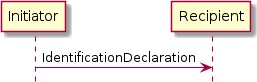
Figure 29. Overview of the UDC Protocol
The Commissionee is the Initiator and the Commissioner is the Recipient.
It is assumed that the user has directed the Initiator to send this message to the Recipient. Upon receipt and before starting a PASE session with the Initiator, it is assumed that the Recipient will query the DNS-SD records for the Initiator, including all TXT records, and then prompt the user for approval and to enter its Onboarding Payload.
Protocol Messages
Table 43. User Directed Commissioning Protocol
Protocol Opcode
Protocol Command Name
Description
Protocol ID = PROTOCOL_ID_USER_DIRECTED_COMMISSIONING
0x00
IdentificationDeclaration
The Identification Declaration message provides the DNS- SD Instance Name of the commissionee requesting commissioning to the commissioner selected by the user.
The following defines the Matter User Directed Commissioning TLV protocol:

namespace matter.protocols {
user-directed-commissioning => PROTOCOL [ Matter:PROTOCOL_ID_USER_DIRECTED_COMMISSIONING ]
{
IdentificationDeclaration => IdentificationDeclaration-struct
}
}
Message format
All UDC messages SHALL be structured as specified in Section 4.4, “Message Frame Format”. All UDC messages are unsecured at the message layer:
The Session ID field SHALL be set to 0.
The Session Type bits of the Security Flags SHALL be set to 0.
The S Flag and DSIZ fields of the Message Flags SHALL be set to 0.
The R Flag of the Exchange Flags for the UDC messages SHALL be set to 0.
For each UDC message, the application payload is the TLV encoding of the message structure as defined below:
Table 44. UDC Messages
Message Name
Payload TLV Encoding
IdentificationDeclaration
IdentificationDeclaration-struct
The other fields of the Message format are not specific to the UDC messages.
Message Exchanges
The flags of the Exchange Flags of the Protocol Header are defined as follows per UDC message:
Message
I Flag
IdentificationDeclaration
1
All UDC messages SHALL be sent unreliably, to an IP address found in a AAAA record associated with the Commissioner Discovery (_matterd._udp) service, using UDP with a destination port as found in the _matterd._udp SRV record. The Initiator MAY send up to 4 retries. Each retransmission SHALL be delayed by at least 100ms from the previous transmission.
The other fields of the Protocol Header are not specific to the UDC messages.
IdentificationDeclaration Message
This message serves to identify the commissionee. It is sent by the commissionee to the commissioner. The commissionee SHALL:
Construct the instanceName based upon the DNS-SD instance name defined in Commissionable Node Discovery.

IdentificationDeclaration-struct => STRUCTURE [ tag-order ]
{
instanceName [1] : OCTET STRING [ length 8 ]
}
Construct and send IdentificationDeclaration.
Device Discovery
Purpose and Scope
The purpose of this section is to describe the process by which a device is discovered in order to commission it onto an operational Fabric.
Depending on the networking technologies supported by a device, discovery and commissioning are possible using Bluetooth Low Energy (BLE), Wi-Fi (IEEE 802.11-2020) technologies, or over IP if a device is already on an IP network.
Devices that utilize Thread (IEEE 802.15.4) networking technology must also support BLE for the purpose of discovery and commissioning. Directly utilizing Thread-based commissioning for device discovery and commissioning is neither specified nor supported.
BLE commissioning utilizes the Generic Access Profile (GAP) for discovery and for connection establishment, and the Generic Attribute Profile (GATT) for credential conveyance.
Wi-Fi commissioning utilizes Soft-AP functionality where the device acts as an Access Point (AP) that doesn’t provide Internet connectivity. Standard Wi-Fi AP advertisement and connection protocols are employed for device discovery and credential conveyance, respectively.
If a device already has network connectivity (over Wi-Fi, Ethernet, or otherwise) a Commissioner may discover such a device using DNS-based Service Discovery (DNS-SD), conveying credentials to the device over IP.
Announcement by Device
This section describes how devices announce their commissionable status to allow a Commissioner to discover the device to be commissioned.
Technology Priority
A device SHALL announce in any order of priority on all of the networking technologies it supports as indicated in the Discovery Capability Bitmask (see Table 36, “Discovery Capabilities Bitmask”). A Commissioner that is aware of the device’s Discovery Capability Bitmask SHALL initiate Device Discovery in any order of priority on all of the networking technologies that are supported by both the Commissioner and the device. A Commissioner that is unaware of the device’s Discovery Capability Bitmask SHALL initiate Device Discovery in any order on all of the networking
technologies it supports out of Wi-Fi Soft-AP, BLE, and on IP network discovery.
Commissioners SHALL always support discovering a device using DNS-based Service Discovery (DNS-SD) for commissioning, irrespective of the Discovery Capabilities Bitmask specified in the Section 5.1.1, “Onboarding Payload Contents”.
Announcement Commencement
A device which is not yet commissioned into a Matter fabric SHALL commence announcing its ability to be commissioned depending on its primary device function and manufacturer-chosen Device Commissioning Flow, per the following table. Nodes already commissioned into one or more Matter fabrics and wishing to announce SHALL ONLY do so using DNS-SD over their operational network (see Section 4.3, “Discovery”). In the interest of privacy, an already-commissioned Node SHALL NOT commence announcement using Bluetooth LE or Wi-Fi Soft-AP technologies.
Primary Device Function
Announcement
Most control originates from a Fabric (excluding Locks and Barrier Access Devices)
SHALL start announcing automatically upon application of power when using Standard commissioning flow. When using User-intent commissioning flow or Custom Commissioning flow, it SHALL NOT start announcing automatically upon application of power.
Most control does not originate from a Fabric (e.g., dishwasher, coffee maker, refrigerator)
SHALL NOT start announcing automatically upon application of power. User-intent commissioning flow or Custom Commissioning flow is required.
Locks and Barrier Access Devices
SHALL NOT start announcing automatically upon application of power. User-intent commissioning flow or Custom Commissioning flow is required.
Note that the above guidelines are in place to avoid unnecessary pollution of the 2.4 GHz spectrum and as a mitigation of the privacy threat created due to unnecessary transmissions by a commissionable device.
If announcement has ceased (see Section 5.4.2.3, “Announcement Duration”), it may be re-initiated via a device-specific user interaction such as a button press or other action defined by the manufacturer and indicated by the methods specified in Section 5.7, “Device Commissioning Flows”.
Announcement Duration
In order to minimize unnecessary pollution of the crowded 2.4 GHz wireless spectrum, a commissionable device SHALL NOT announce for a duration longer than 15 minutes after announcement commences. This should provide ample time for a user to commission a range of devices, including time to download, install and launch applications, transit rooms within a home, etc.
Note that devices MAY choose to announce for less time in order to conserve battery life or for other device-specific reasons. Note that an announcement duration that is too short may result in a poor setup experience for users. Shorter announcement intervals SHOULD only be employed to
meet otherwise unattainable device functionality/requirements. To help strike a balance between a good setup experience and conserving battery life, a device SHALL NOT announce for a duration of less than 3 minutes after announcement commences.
A failed attempt to commission does not restart or delay the timeout. Moreover, this timeout applies only to cessation of announcements and not to abortion of connections, i.e., a connection SHOULD NOT abort prematurely upon expiration of the announcement duration.
Discovery Information
This section details the information advertised by a commissionable Node.
Field
Length
Is Required?
Discriminator
12-bit
Yes
Vendor ID
16-bit
No
Product ID
16-bit
No
Extended Data
Variable
No
Discriminator
A 12-bit value matching the field of the same name in the Setup Code.
Vendor ID
A 16-bit value identifying the device manufacturer (see Section 2.5.2, “Vendor Identifier (Vendor ID, VID)”).
Product ID
A 16-bit value identifying the product (see Product ID).
Extended Data
Extended Data MAY be made available by commissionable Nodes. This data SHALL be encoded using a standard TLV encoding defined in this section. The location of this data varies based on the Node’s commissioning networking technology.
This extended data SHALL be encoded as a TLV structure tagged with an anonymous tag.
The members of this structure SHALL use context-specific tags with the values and meanings shown in the table below.
Tag
Value
Member type
Member Description
RotatingIdTag
0x00
octet string
Rotating Device Identifier
Rotating Device Identifier
Some device makers need a way to uniquely identify a device before it has been commissioned for vendor-specific customer support purposes. For example, the device maker may need this to
identify factory software version and related features, manufacturing date, or to assist in recovery when a setup code has been lost or damaged. In order to avoid privacy issues associated with a fixed unique identifier, devices MAY utilize a Rotating Device Identifier for identification purposes. A Rotating Device Identifier is similar to a serial number but rotates at pre-defined moments.
The Rotating Device Identifier provides a non-trackable identifier which is unique per-device and that can be used in one or more of the following ways:
Provided to the vendor’s customer support for help in pairing or establishing Node provenance;
Used programmatically to obtain a Node’s Passcode or other information in order to provide a simplified setup flow. Note that the mechanism(s) by which the Passcode may be obtained is outside of this specification. If the Rotating Device Identifier is to be used for this purpose, the system implementing this feature SHALL require proof of possession by the user at least once before providing the Passcode. The mechanism for this proof of possession, and validation of it, is outside of this specification.
The Rotating Device Identifier is an optional feature for a Node to implement and an optional feature for a Commissioner to utilize. The algorithm used for generating a Rotating Device Identifier SHALL meet the following security and privacy requirements:
It SHALL be irreversible in such a way that:
It SHALL prevent recovery of a unique identifier for the device by entities that do not already have access to the set of possible unique identifiers.
Leaking of a common key or equivalent could not be used to recover a unique identifier for all devices sharing the common key.
It SHALL protect against long-term tracking by rotating upon each commencement of advertising.
It SHALL have a total of at least 64 bits of entropy and SHOULD preferably have more, up to 256 bits.
It SHALL NOT contain a fixed identifier such as a serial number.
The Rotating Device Identifier Algorithm below meets these requirements. A Node that implements the Rotating Device Identifier SHALL use either the Rotating Device Identifier Algorithm or a different algorithm which has been approved and verified by the Connectivity Standards Alliance for this purpose and which meets the same set of security and privacy requirements listed above.
The Rotating Device Identifier Algorithm employs a key derivation algorithm that combines a monotonically increasing lifetime counter with a unique per-device identifier.
The unique identifier SHALL consist of a randomly-generated 128-bit or longer octet string which SHALL be programmed during factory provisioning or delivered to the device by the vendor using secure means after a software update.
The unique identifier SHALL be protected against reading or writing over the air after initial introduction into the device, and stay fixed during the lifetime of the device.
The lifetime counter SHALL be an integer at least 16 bits in size, incremented upon each

Rotating Device ID = Rotation Counter || Crypto_KDF(
inputKey := Unique ID, salt:= Rotation Counter, info := "RotatingDeviceID", len := 128)
commencement of advertising, and wrapping when the maximum value is reached. The Rotating Device Identifier Algorithm is defined as follows:
(where || is the concatenation operation)
The rotation counter is encoded as 2 bytes using little-endian encoding in the above algorithm, everywhere it appears.
The Rotating Device ID is the concatenation of the current rotation counter and the 16 bytes of the Crypto_KDF result.
TLV Example
Extended data containing just a Rotating Device Identifier would be encoded as the following bytes:
Offset
Data
Comments
0x00
0x15
Control byte for structure with anonymous tag
0x01
0x30
Control byte for octet string with 1-byte length and a context-specific tag
0x02
0x00
Context-specific tag for Rotating Device Identifier
0x03
0x12
Length of Rotating Device Identifier (e.g. 18 bytes)
0x04
0xXX..0x XX
Rotating Device Identifier
0x16
0x18
End of container
Using BLE
This section provides details of how a device announces its commissionable status using BLE technology. Nodes currently commissioned into one or more fabrics SHALL NOT employ this method.

NOTE Need to add link(s) to BLE specification.
Device Role
Commissionable devices SHALL implement the role of a Generic Access Profile (GAP) Peripheral.
Channels
There are three advertising channels used by BLE. All three channels SHOULD be used by commissionable devices for BLE advertising.
Interval
Commissionable devices SHOULD use an Advertising Interval between 20 ms and 60 ms for the first 30 seconds and a value between 150 ms to 1200 ms for the rest of the Announcement duration. Shorter intervals typically result in shorter discovery times.
Advertising Mode
Commissionable devices SHALL use the GAP General Discoverable mode, sending connectable undirected advertising events.
Advertising Address
To ensure privacy, commissionable devices SHALL use LE Random Device Address (see Bluetooth® Core Specification 4.2 Vol 6, Part B, Section 1.3.2.1 "Static device address") for BLE Advertising and SHALL change it at least on every boot.
Advertising Data
In order to reduce 2.4 GHz spectrum congestion due to active BLE scanning, and to extend battery life in battery-powered devices, all critical data used for device discovery is contained in the Advertising Data rather than the Scan Response Data. This allows a BLE Commissioner to passively scan (i.e., not issue Scan Requests upon receiving scannable advertisements) and still be able to receive all information needed to commission a device.
Note that if additional vendor-specific information is to be conveyed and does not fit within the Advertising Data, it may be included in the Scan Response Data. See Section 5.4.2.8, “Manufacturer- specific data” for details on including vendor-specific information.
The following table details the contents of the Advertising PDU payload:
Byte
Value
Description
0
0x02
AD[0] Length == 2 bytes
1
0x01
AD[0] Type == 1 (Flags)
2
0x06
Bit 0 (LE Limited Discoverable Mode) SHOULD be set to 0 Bit 1 (LE General Discoverable Mode) SHOULD be set to 1
If only BLE is supported, this value SHOULD be set to 0x06. If BR/EDR functionality is supported by a commissionable device, this value SHOULD be set accordingly.
3
0x0B
AD[1] Length == 11 bytes
4
0x16
AD[1] Type == 0x16 (Service Data - 16-bit UUID)
5-6
0xFFF6
16-bit Matter UUID assigned by Bluetooth SIG
7
0x00
Matter BLE OpCode == 0x00 (Commissionable) Values 0x01 - 0xFF are reserved
8-9
Variable
Bits[15:12] == 0x0 (Advertisement version)
Bits[11:0] == 12-bit Discriminator (see Section 5.4.2.4.1, “Discriminator”)
Byte
Value
Description
10-11
Variable
16-bit Vendor ID (see Section 5.4.2.4.2, “Vendor ID”) Set to 0, if elided
12-13
Variable
16-bit Product ID (see Section 5.4.2.4.3, “Product ID”) Set to 0, if elided
14
Fixed
Bit[0] == Additional Data Flag (see Section 5.4.2.5.7, “GATT-based Additional Data”)
Bits[7:1] are reserved for future use and SHALL be clear (set to 0)
Devices MAY choose not to advertise either the VID and PID, or only the PID due to privacy or other considerations. When choosing not to advertise both VID and PID, the device SHALL set both VID and PID fields to 0. When choosing not to advertise only the PID, the device SHALL set the PID field to 0. A device SHALL NOT set the VID to 0 when providing a non-zero PID.
GATT-based Additional Data
When the Additional Data Flag is set in the Matter Service Data in the BLE Advertisement, the commissioner MAY access additional commissioning-related data via an unencrypted read-only GATT characteristic C3 (see Table 31, “BTP GATT service”).
The value of the C3 characteristic SHALL be set to the Extended Data payload of the Discovery Information (see Section 5.4.2.4.4, “Extended Data”).
Using Wi-Fi Temporary Access Points (Soft-AP)
This section details how a device advertises its commissionable state using Wi-Fi Soft-AP functionality, wherein the device acts as a Wi-Fi Access Point (AP) that doesn’t provide Internet access and a Commissioner acts as a Wi-Fi station client and associates with the device’s AP in order to commission it over IPv6. Nodes currently commissioned into one or more fabrics SHALL NOT employ this method.
Device Role
The device operates as an Access Point, transmitting Beacons and responding to Probe Requests by sending Probe Responses per the rules specified in IEEE 802.11-2020.
The Commissioner associates with the Device’s temporary Wi‑Fi access point. Once Commissioner and Device have established link-layer connectivity at the Wi‑Fi layer, both Commissioner and Device configure themselves unique IPv6 link-local addresses, and then Device Discovery proceeds as for the cases using existing IP-bearing network.
AP Operating Parameters
The following table specifies the AP operational parameters:
Parameter
Value
SSID
MATTER-ddd-vvvv-pppp
Note that all above elements are present in the QR code for commissioners that require an exact SSID for scanning/connection.
Some devices may choose not to advertise the VID and/or PID
NOTE due to privacy or other considerations. These devices SHOULD advertise the value 0 instead of the VID/PID.
Hidden SSID
SSID SHALL NOT be hidden as the device may need to be chosen using a mobile OS "network picker" on older mobile OS versions.
BSSID
SHALL be randomly generated on each boot for privacy/tracking reasons. Broadcast bit SHALL be clear, Locally-administered bit SHALL BE set.
Channel
SHALL be chosen from any valid 2.4 GHz ISM channel based on regulatory domain at boot. SHOULD choose randomly from 1, 6, or 11. Vendors may need to choose a specific channel for device-specific reasons.
Security
None
Beacon Interval
100 TUs
DTIM Interval
Not specified (Commissioner power management not expected)
ddd is the 12-bit Discriminator in hex digits
vvvv is the 16-bit Vendor ID (VID) in hex digits
pppp is the 16-bit Product ID (PID) in hex digits

Matter Vendor-specific IE
This section defines the Information Element (IE) and attributes for Matter devices that support Wi- Fi Soft-AP for commissioning. The Matter IE SHALL be carried in the Wi-Fi Soft-AP Beacon and Probe Response frames.
A Vendor Specific IE format as defined in IEEE 802.11-2020 SHALL be used to define the Matter IE in this specification. The format for the Matter IE is shown in Table 45, “Matter Information Element format”. Little-endian encoding is used for all fields and subfields in the Matter IE format.
Table 45. Matter Information Element format
Field
Size (Octets)
Value (Hex)
Description
Element ID
1
0xDD
IEEE 802.11-2020 vendor specific information element
Length
1
Variable
Length of the following fields in the IE in octets. The Length field is variable and set to 4 plus the total length of the Matter Attributes
OUI
3
4A:19:1B
Connectivity Standards Alliance OUI
Field
Size (Octets)
Value (Hex)
Description
OUI Type
1
0x00
Identifying the type and version of the Matter IE Values 0x01 - 0xFF are reserved
Matter attributes
Variable
Variable
One or more Matter attributes
The Matter attributes are defined to have a common general format consisting of a one octet Matter attribute identifier field, a one octet Length field, and a variable-length attribute-specific information field, as shown in Table 46, “Matter Attribute format”.
Table 46. Matter Attribute format
Field
Size (Octets)
Value (Hex)
Description
Attribute ID
1
Variable
identifies the type of Matter attribute.
Values defined in Table 47, “Matter Attribute list”.
Length
1
Variable
Length of the following fields in the attribute
Attribute Body
Variable
Variable
Matter attribute specific information fields
The Table 47, “Matter Attribute list” defines the Matter attributes that SHALL be included in the Wi- Fi Soft-AP Matter IE.
Table 47. Matter Attribute list
Attribute ID (Hex)
Description
0x00
Reserved
0x01
Device OpCode
0x02
Device Information
0x03
Rotating Device Id
0x04 - 0xFF
Reserved
Device State Matter attribute
The format of Device OpCode (Operational Code) Matter attribute is shown in Table 48, “Device State Matter Attribute format”.
Table 48. Device State Matter Attribute format
Field
Size (Octets)
Value (Hex)
Description
Attribute ID
1
0x01
Device OpCode attribute
Length
1
0x01
Length of the following fields in the attribute
Field
Size (Octets)
Value (Hex)
Description
Attribute Body
1
Variable
0x00 : Commissionable
Values 0x01 - 0xFF are reserved
Device Information attribute
The format of Device Information Matter attribute is shown in Table 49, “Device Information Matter Attribute format”.
Table 49. Device Information Matter Attribute format
Field
Size (Octets)
Value (Hex)
Description
Attribute ID
1
0x02
Vendor ID attribute
Length
1
0x06
Length of the following fields in the attribute
Device Discriminato r
2
Variable
b0 - b11 : 12-bit discriminator (see Section 5.4.2.4.1, “Discriminator”)
b12 - b15 : Reserved, set to zero
VID
2
Variable
16-bit Vendor ID (see Section 5.4.2.4.2, “Vendor ID”) Set to 0, if elided
PID
2
Variable
16-bit Product ID (see Section 5.4.2.4.3, “Product ID”) Set to 0, if elided
Devices MAY choose not to advertise either the VID and PID, or only the PID due to privacy or other considerations. When choosing not to advertise both VID and PID, the device SHALL set both VID and PID fields to 0. When choosing not to advertise only the PID, the device SHALL set the PID field to 0. A device SHALL NOT set the VID to 0 when providing a non-zero PID.
Rotating Device Id attribute
The format of Rotating Device Id is shown in Table 50, “Rotating Device Id Attribute format”.
Table 50. Rotating Device Id Attribute format
Field
Size (Octets)
Value (Hex)
Description
Attribute ID
1
0x03
Rotating Device Id attribute
Length
1
Variable
Length of the following fields in the attribute
RDI
Variable
Variable
Rotating Device Identifier, encoded as a variable length upper-case hexadecimal string, including any leading zeroes.
Additional Data
Additional data, using the encoding defined above (see Section 5.4.2.4, “Discovery Information”),
MAY be included in the Matter IE as an additional attribute, for more information about IE attribute (see Matter Information Element)
DHCP
A DHCP Server SHALL be implemented on the device if Soft-AP commissioning is used. Though Soft- AP commissioning relies on link-local IPv6 communication, some mobile OSes generate lack-of- connectivity warnings to the user if an IPv4 address is not obtained via a DHCP server. The following table specifies the DHCP server operational parameters:
Parameter
Value
Prefix
192.168.226/24 (avoid 192.168.1/24, 192.168.0/24, etc.)
Server IPv4 Address
192.168.226.1
Range
192.168.226.2 to 192.168.226.254.
Lease time
15 minutes (same as discovery timeout)
Using Existing IP-bearing Network
This section details how a device that is already connected to an IP-bearing network advertises its commissionable state. The discovery protocols leverage IETF Standard DNS-based Service Discovery [RFC 6763]. A device SHALL use multicast DNS [RFC 6762] on Wi-Fi and Ethernet networks to make itself discoverable. On Thread networks, a device SHALL use the Service Registration Protocol [SRP] and an Advertising Proxy [AdProx] running on a Thread Border Router to make itself discoverable. Additional details on application of the above protocols in Matter is found in Section 4.3, “Discovery”. The encoding of the information required for discovery during the commissioning process is covered in Section 4.3.1, “Commissionable Node Discovery”.
Manufacturer-specific data
If needed, manufacturer-specific data MAY be advertised by a commissionable device using one of the following mechanisms, based on the supported commissioning technology. Commissioners receiving this data SHOULD treat it as opaque unless they have the need to and possess the ability to correctly interpret the information conveyed.
Using BLE
Any manufacturer-specific data may be included as a Manufacturer Specific Data AD type in the Advertising Data or in the Scan Response data.
Note that to receive Scan Response data information the Commissioner has to perform BLE active scanning that, in addition to creating additional traffic in the shared 2.4 GHz unlicensed band, can delay device discovery and connection, increasing the overall time required to commission a device.
Using Wi-Fi
Any manufacturer-specific data SHOULD be conveyed using the Vendor-specific Information
Element (IE) mechanism per IEEE 802.11-2020. Non-Matter-specific information SHALL NOT be included in the Matter-specified Vendor-specific IE (see Section 5.4.2.6.3, “Matter Vendor-specific IE”).
Discovery by Commissioner
How a Commissioner discovers a commissionable device depends on the networking technologies that device and the Commissioner supports (see Section 5.4.2.1, “Technology Priority”). Though not all networking technologies must be supported by every device (see Table 36, “Discovery Capabilities Bitmask”), a Commissioner SHALL support Commissioning (see Section 5.5, “Commissioning Flows”) using existing IP network and over BLE (if having such interface) and SHOULD support commissioning over Wi-Fi Soft-AP.
The following sections detail Commissioner behavior for each of these networking technologies. Though a QR or Manual Pairing code may be scanned or entered prior to discovery, it is not required to do so. However, after scan/entry of the code, the Discriminator, VID and PID elements are available to ensure that the intended device is discovered before proceeding to the connection phase of commissioning.
Using BLE
Commissioners SHALL implement the role of a GAP Central. To discover a commissionable device advertising over BLE, a Commissioner SHALL perform a BLE scan across all three advertising channels with a sufficient dwell time, interval, and overall duration of scan. In order to promote quick discovery it is recommended that a Commissioner scan as aggressively as possible within the Commissioner device functionality/UX constraints. In addition, if manufacturer-specific data is not needed, a passive scan (i.e., one that only listens for Advertisement PDUs and does not issue Scan Request PDUs).
If discovery procedure is user initiated the scan interval SHOULD be set between 30 ms and 60 ms, and the scan window SHOULD be set to 30 ms. If discovery procedure is not user initiated (i.e., the Commissioner is scanning in the background), the device may use more relaxed scan, for example, the scan interval set to 1.28 seconds and scan window set to 11.25 ms.
Note: Recommended values are defined in Appendix A: Timers and Constants of Bluetooth® Core Specification 4.2, Vol 3, Part C.
Using Wi-Fi
To discover a commissionable device acting as a Soft-AP and advertising its commissionable status, a Commissioner SHALL perform a scan of all 2.4 GHz Wi-Fi channels allowed per its operational regulatory domain. Given that channels 1, 6, and 11 are preferred (see Section 5.4.2.6.2, “AP Operating Parameters”), scanning of those channels SHOULD be prioritized to minimize discovery time. Where practical and allowed by regulations, active scanning using Probe Requests SHOULD be also be used to help minimize discovery time. However, Commissioners that are always scanning as a background activity SHOULD do so passively (i.e., SHOULD NOT send Probe Requests) in order to reduce unnecessary transmissions in the shared 2.4 GHz spectrum.
Using Existing IP-bearing Network
To discover a commissionable device over an existing IP-bearing network connection, the Commissioner shall perform service discovery using DNS-SD as detailed in Section 4.3, “Discovery”, and more specifically in Section 4.3.1, “Commissionable Node Discovery”.
Commissioning Flows
There are two commissioning flows depending upon the networking capability of the Commissioner and Commissionee, namely concurrent connection commissioning flow and non- concurrent connection commissioning flow.
A Commissioner and Commissionee with concurrent connection have the ability to maintain two network connections simultaneously. One connection is between the Commissioner (or Commissionee) and the operational network (e.g., home Wi-Fi network or Thread network) that the Commissionee is being programmed to join. The second connection is between the Commissioner and Commissionee for commissioning as is referred to as commissioning channel. A Commissioner and Commissionee with non-concurrent connection capability cannot be simultaneously connected to both the operational network that the Commissionee is being configured to join, and the commissioning channel.
The two connections MAY either be on the same or on different networking interfaces. For example, a Commissioner uses its Wi-Fi interface to connect to the operational network, but use its Bluetooth Low Energy interface for commissioning.
To determine whether a Commissionee has concurrent or non-concurrent connection capability, the Commissioner can use the SupportsConcurrentConnection attribute of the General Commissioning Cluster.
Commissioning SHALL be a time-bound process that completes before expiration of a fail-safe timer. The fail-safe timer SHALL be set at the beginning of commissioning. If the fail-safe timer expires prior to commissioning completion, the Commissioner and Commissionee SHALL terminate commissioning. Successful completion of commissioning SHALL disarm the fail-safe timer.
A Commissionee that is ready to be commissioned SHALL accept the request to establish a PASE session with the first Commissioner that initiates the request. When a Commissioner is either in the process of establishing a PASE session with the Commissionee or has successfully established a session, the Commissionee SHALL NOT accept any more requests for new PASE sessions until session establishment fails or the successfully established PASE session is terminated on the commissioning channel (see CloseSession in Secure Channel Status Report Messages). In the event a CloseSession status message is sent or received:
If the fail-safe timer is armed, the fail-safe timer SHALL be considered expired and the cleanup steps detailed in Section 11.9.7.2, “ArmFailSafe Command” SHALL be executed.
If the commissioning window is still open, the Commissionee SHALL continue listening for commissioning requests.
In order to avoid locking out the Commissionee from accepting new PASE session requests indefinitely, a Commissionee SHALL expect a PASE session to be established within 60 seconds of
receiving the initial request. This means the Commissionee SHALL expect to receive the PAKE3 message within 60 seconds after sending a PBKDFParamResponse in response to a PBKDFParamRequest message from the Commissioner to establish a PASE session. If the PASE session is not established within the expected time window the Commissionee SHALL terminate the current session establishment using the INVALID_PARAMETER status code as described in Section 4.10.1.3, “Secure Channel Status Report Messages”.
The commissioning commands and attributes are defined in Clusters (see Section 11.8, “Network Commissioning Cluster”, Section 11.9, “General Commissioning Cluster”, Section 11.13, “Thread Network Diagnostics Cluster”, and Section 11.14, “Wi-Fi Network Diagnostics Cluster”) and are sent, written, or read using the Interaction Model (see Interaction Model).
Figure 30, “Concurrent connection commissioning flow” and Figure 31, “Non-concurrent connection commissioning flow” depict the commissioning flow between the Commissioner and Commissionee with concurrent connection ability and non-concurrent connection ability, respectively. The specific steps are described below. Unless indicated otherwise, a commissioner SHALL complete a step, including waiting for any responses to commands it sends in that step, before moving on to the next step.
The Commissioner initiating the commissioning SHALL have regulatory and fabric information available, and SHOULD have accurate date, time and timezone.
Commissioner and Commissionee SHALL find each other over networking interfaces such as Bluetooth, Wi-Fi, or Ethernet using the process of discovery and establish a commissioning channel between each other (see Section 5.4, “Device Discovery”).
Commissioner and Commissionee SHALL establish encryption keys with PASE (see Section 4.13.1, “Passcode-Authenticated Session Establishment (PASE)”) on the commissioning channel. All subsequent messages on the commissioning channel are encrypted using PASE-derived encryption keys. Upon completion of PASE session establishment, the Commissionee SHALL autonomously arm the Fail-safe timer for a timeout of 60 seconds. This is to guard against the Commissioner aborting the Commissioning process without arming the fail-safe, which may leave the device unable to accept additional connections.
Commissioner SHALL re-arm the Fail-safe timer on the Commissionee to the desired commissioning timeout within 60 seconds of the completion of PASE session establishment, using the ArmFailSafe command (see Section 11.9.7.2, “ArmFailSafe Command”). A Commissioner MAY obtain device information including guidance on the fail-safe value from the Commissionee by reading BasicCommissioningInfo attribute (see Section 11.9.6.2, “BasicCommissioningInfo Attribute”) prior to invoking the ArmFailSafe command.
Commissioner SHALL configure regulatory information in the Commissionee if it has at least one instance of Network Commissioning cluster on any endpoint with either the WI (i.e. Wi-Fi) or TH (i.e. Thread) feature flags set in its FeatureMap. Commissioner SHOULD configure UTC time, timezone, and DST offset, if the Commissionee supports the time cluster. The order of configuration of this information is not critical. The UTC time is configured using SetUtcTime command (see Section 11.16.7.1, “SetUtcTime Command”) while timezone and DST offset are set through TimeZone (see Section 11.16.6.6, “TimeZone Attribute”) and DstOffset attribute (see Section 11.16.6.7, “DstOffset Attribute”), respectively. The regulatory information is configured using SetRegulatoryConfig (see Section 11.9.7.4, “SetRegulatoryConfig Command”).
Commissioner SHALL establish the authenticity of the Commissionee as a certified Matter device (see Section 6.2.3, “Device Attestation Procedure”).
If the Commissionee fails the Device Attestation Procedure, for any reason, the Commissioner MAY choose to either continue to the Commissioning, or terminate it, depending on implementation-dependent policies.
Upon failure of the procedure, the Commissioner SHOULD warn the user that the Commissionee is not a fully trusted device, and MAY give the user the choice to authorize or deny the commissioning. Such a warning enables user choice in Commissionee trust on their Fabric, for development workflows, as well as homebrew device development. Such a warning SHOULD contain as much information as the commissioner can provide about the Commissionee, and SHOULD be adapted to the reason of the failure, for example by being different between the case of an expired certificate and the case of a failed signature verification.
Reasons for failing the Device Attestation procedure MAY include, but are not limited to, the following:
The Commissionee being of a device type currently in development or not yet certified (see certification_type in the Certification Declaration).
The Commissionee’s PAA not being in the Commissioner’s trusted set.
The Commissioner having obtained knowledge that a PAA or PAI certificate presented has been revoked, or that the particular Device Attestation Certificate has been revoked.
The Commissionee failing to prove possession of the Device Attestation private key, either by programming error, malicious intent or other reasons.
One of the elements of the Commissionee’s Device Attestation Certificate chain not meeting the policy validation steps of the Device Attestation Procedure, including errors on validity period.
If a Commissioner denies commissioning for any reason, it SHOULD notify the user of the reason with sufficient details for the user to understand the reason, so that they could determine if it would be possible to commission the device using a different Commissioner.
Following the Device Attestation Procedure yielding a decision to proceed with commissioning, the Commissioner SHALL request operational CSR from Commissionee using the CSRRequest command (see Section 11.18.7.5, “CSRRequest Command”). The CSRRequest command will cause the generation of a new operational key pair at the Commissionee.
Commissioner SHALL generate or otherwise obtain an Operational Certificate containing Operational ID after receiving the CSRResponse command from the Commissionee (see Section 11.18.7.5, “CSRRequest Command”), using implementation-specific means.
Commissioner SHALL install operational credentials (see Figure 38, “Node Operational Credentials flow”) on the Commissionee using the AddTrustedRootCertificate and AddNOC commands.
If the Commissioner had determined that the necessary Trusted Root Certificate was already present, it MAY omit AddTrustedRootCertificate. See Section 11.18.7.13, “AddTrustedRootCertificate Command” for details.
Note that the AddNOC command will fail if the necessary Trusted Root Certificate had not
been previously installed by the Commissioner or a previous Commissioner. See Section 11.18.7.8, “AddNOC Command” for details.
Commissioner MAY configure the Access Control List (see Access Control Cluster) on the Commissionee in any way it sees fit, if the singular entry added by the AddNOC command in the previous step granting Administer privilege over CASE authentication type for the Node ID provided with the command is not sufficient to express its desired access control policies.
If the Commissionee both supports it and requires it, the Commissioner SHALL configure the operational network at the Commissionee using commands such as AddOrUpdateWiFiNetwork (see Section 11.8.8.4, “AddOrUpdateWiFiNetwork Command”) and AddOrUpdateThreadNetwork (see Section 11.8.8.5, “AddOrUpdateThreadNetwork Command”). A Commissionee requires network commissioning if it is not already on the desired operational network. A Commissionee supports network commissioning if it has any NetworkCommissioning cluster instances. A Commissioner MAY learn about the networks visible to the Commissionee using ScanNetworks command (see Section 11.8.8.2, “ScanNetworks Command”).
The Commissioner SHALL trigger the Commissionee to connect to the operational network using ConnectNetwork command (see Section 11.8.8.10, “ConnectNetwork Command”) unless the Commissionee is already on the desired operational network.
Finalization of the Commissioning process begins. An Administrator configured in the ACL of the Commissionee by the Commissioner SHALL use Operational Discovery to discover the Commissionee. This Administrator MAY be the Commissioner itself, or another Node to which the Commissioner has delegated the task.
The Administrator SHALL open a CASE (see Section 4.13.2, “Certificate Authenticated Session Establishment (CASE)”) session with the Commissionee over the operational network.
The Administrator having established a CASE session with the Commissionee over the operational network in the previous steps SHALL invoke the CommissioningComplete command (see Section 11.9.7.6, “CommissioningComplete Command”). A success response after invocation of the CommissioningComplete command ends the commissioning process.
While the Administrator of steps 13-15 will, in many situations, be the Commissioner Node itself, it MAY be a different Node that was configured by the Commissioner to have Administer privilege against the Commissionee’s General Commissioning Cluster. This is to support flexibility in finalizing the Commissioning. From a Commissionee’s perspective, all Nodes with Administer privilege in the Commissionee’s ACL are equivalent once the Node has a Node Operational Certificate and associated Node Operational Identifier on the Fabric into which it was just commissioned.
A Commissioner MAY configure UTC time, Operational ID, and Operational certificates, etc., information over an arbitrary number of interactions at the Commissionee, over the operational network after the commissioning is complete, or over the commissioning channel after PASE- derived encryption keys are established during commissioning.
In concurrent connection commissioning flow the commissioning channel SHALL terminate after successful step 15 (CommissioningComplete command invocation). In non-concurrent connection commissioning flow the commissioning channel SHALL terminate after successful step 12 (trigger joining of operational network at Commissionee). The PASE-derived encryption keys SHALL be deleted when commissioning channel terminates. The PASE session SHALL be terminated by both
Commissioner and Commissionee once the CommissioningComplete command is received by the Commissionee.
In both concurrent connection commissioning flow and non-concurrent connection commissioning flow, the Commissioner MAY choose to continue commissioning and override the failure in step 6 (Commissionee attestation).
Commissioning Flows Error Handling
Overall, all Commissioning operations employ actions using cluster attributes and commands that are also, in certain cases, available during normal steady-state operation once commissioned.
Whenever the Fail-Safe timer is armed, Commissioners and Administrators SHALL NOT consider any cluster operation to have timed-out before waiting at least 30 seconds for a valid response from the cluster server. Some commands and attributes with complex side-effects MAY require longer and have specific timing requirements stated in their respective cluster specification.
Some request commands used for Commissioning and administration have a 'Breadcrumb' argument. When set, this argument SHALL be used to update the value of the Breadcrumb Attribute as a side-effect of successful execution of those commands. On command failures, the Breadcrumb Attribute SHALL remain unchanged.
In concurrent connection commissioning flow, the failure of any of the steps 2 through 10 SHALL result in the Commissioner and Commissionee returning to step 2 (device discovery and commissioning channel establishment) and repeating each step. The failure of any of the steps 11 through 15 in concurrent connection commissioning flow SHALL result in the Commissioner and Commissionee returning to step 11 (configuration of operational network information). In the case of failure of any of the steps 11 through 15 in concurrent connection commissioning flow, the Commissioner and Commissionee SHALL reuse the existing PASE-derived encryption keys over the commissioning channel and all steps up to and including step 10 are considered to have been successfully completed.
In non-concurrent connection commissioning flow, the failure of any of the steps 2 through 15 SHALL result in the Commissioner and Commissionee returning to step 2 (device discovery and commissioning channel establishment) and repeating each step.
Commissioners that need to restart from step 2 MAY immediately expire the fail-safe by invoking the ArmFailSafe command with an ExpiryLengthSeconds field set to 0. Otherwise, Commissioners will need to wait until the current fail-safe timer has expired for the Commissionee to begin accepting PASE again.
In both concurrent connection commissioning flow and non-concurrent connection commissioning flow, the Commissionee SHALL exit Commissioning Mode after 20 failed attempts.
Once a Commissionee has been successfully commissioned by a Commissioner into its fabric, the commissioned Node SHALL NOT accept any more PASE requests until any one of the following conditions is met:
Device is factory-reset.
Device enters commissioning mode.
Ongoing administration of Nodes by Administrators employs many of the same clusters and constraints related to Fail-Safe timer and cluster operation time-outs used for initial or subsequent Commissioning into new Fabrics. The respective cluster specifications for the Node Operational Credentials Cluster and the Network Commissioning Cluster reflect the necessary usage of the ArmFailSafe and CommissioningComplete commands of the General Commissioning Cluster to achieve consistent state during administrative operations.
Commissioning Flow Diagrams
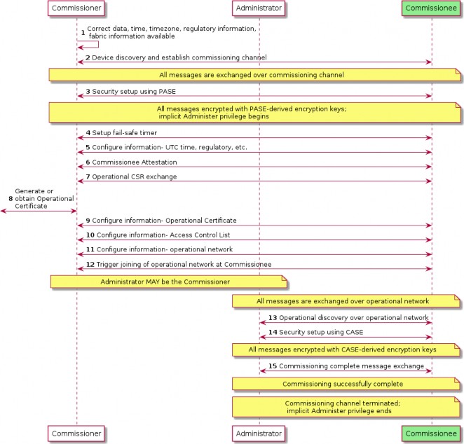
Figure 30. Concurrent connection commissioning flow
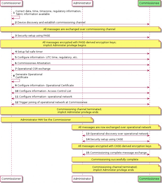
Figure 31. Non-concurrent connection commissioning flow
Administrator Assisted Commissioning Flows
Introduction
In this method, a current Administrator of a Node first sends the Open Commissioning Window command to the Node over a CASE session. The new Administrator MUST already have network connectivity and complete commissioning based on the two flows described below.
The commands for these flows are defined in Section 11.19, “Administrator Commissioning Cluster”.
Basic Commissioning Method (BCM)
This method is OPTIONAL for Nodes and Administrators/Commissioners to implement. In this method, the current Administrator MUST send the Open Basic Commissioning Window command to the Node over a CASE session. The Node SHALL advertise its presence over DNS-SD (see Section 5.4.2.7, “Using Existing IP-bearing Network” and Commissionable Node Discovery) after receiving the Open Basic Commissioning Window command.
The new Administrator’s Commissioner then completes commissioning with the Node using similar Commissioning flow as it would do for a factory-new device (although note that IP channel is used for discovery). It can either scan the QR code format or use the Manual Pairing Code format of the Section 5.1, “Onboarding Payload” of the Node.
The following steps describe a possible sequence of events for BCM commissioning:
Current Administrator puts the Node in Open Basic Commissioning Window for a specified time window, and receives success response from the Node on the Open Basic Commissioning Window command.
When the targeted Node is a SED, the current Administrator can guide the user to perform some action to 'wake' the device from its sleep cycle.
New Administrator completes commissioning within the prescribed window using steps outlined in Figure 30, “Concurrent connection commissioning flow”.
Enhanced Commissioning Method (ECM)
This method is MANDATORY for Nodes and Commissioners/Administrators to implement. When using ECM, the Node’s current Administrator instructs the Node over a CASE session, to go into Open Commissioning Window. It SHALL choose a new RANDOM passcode and SHALL compute and send the corresponding PAKE passcode verifier to the Node. Actual value of the passcode SHALL NOT be sent to the Node. The current Administrator then presents the new passcode and discriminator as described below. The Node SHALL advertise its presence over DNS-SD (see Section 5.4.2.7, “Using Existing IP-bearing Network” and Commissionable Node Discovery) after receiving the Open Commissioning Window command. Sleepy Nodes SHOULD include the optional SII key in their TXT advertisement.
Presentation of Onboarding Payload for ECM
Presentation of the passcode and other relevant information SHALL be done at least with one or more of the methods below, depending on the capabilities of the first Administrator opening the OCW:
If a user interface display is supported, the temporary Onboarding Payload SHALL be displayed using a textual representation of the Manual Pairing Code, using the 11-digit variant: it SHALL NOT contain the VENDOR_ID or PRODUCT_ID as the onboarding of the node(s) using the ECM cannot be subject to User-Intent or Custom Flows.
If a user interface display is supported, the temporary Onboarding Payload SHOULD also be displayed using the definitions included in Section 5.1.3, “QR Code” subject to the following constraints:
If only a single Node is being subjected to the ECM, the Vendor ID and Product ID in the onboarding payload SHALL be the same as those of that Node.
If multiple Nodes are being subjected to the ECM using the same onboarding payload, the Vendor ID SHALL be set to 0x0000 (Matter Standard) and the Product ID SHALL be set to 0x0000 (consistent with the value used for not advertising a Product ID in Device Announcement) .
The Custom Flow element SHALL be set to 0 to indicate standard flow.
The Discovery Capabilities Mask SHALL have ONLY bit 2 set to indicate the Node is only discoverable on the IP network.
The Passcode element SHALL be set by the existing Administrator to the same value as the passcode chosen for this ECM operation.
The Discriminator element SHALL be set by the existing Administrator to the same value as the Discriminator parameter in Section 11.19.8.1, “OpenCommissioningWindow (OCW) Command”.
If multiple Nodes are subjected to ECM, the Section 5.1.5, “TLV Content” SHALL contain an entry with kTag_NumberofDevices containing the number of devices that are expected to participate in the onboarding with this ECM operation.
When the Commissioning Timeout parameter of the OCW command is set to less than the allowed maximum (15 minutes), the Section 5.1.5, “TLV Content” SHALL contain an entry with kTag_CommissioningTimeout containing the value of the Commissioning Timeout parameter used for this ECM operation.
If only audio output is supported, the temporary Onboarding Payload SHALL be delivered using a voice prompt of the Manual Pairing Code format. A method SHOULD be available for the user to have the pairing code repeated.
Remote UIs, both visual and audio — such as a manufacturer-specific mobile app or a web UI — are expressly permitted in the set of acceptable mechanisms for conveyance of the onboarding information.
This method allows a current Administrator to set multiple Nodes for commissioning with a new administrator with an appropriate Commissioning Window, by turning on Open Commissioning Window and sending the PAKE passcode verifier to a series of Nodes. The new Administrator uses the information in Manual Pairing Code to discover the Nodes that are in Commissioning mode and commission them using the new passcode.
The following steps describe a possible sequence of events for ECM commissioning:
Current Administrator puts the Node(s) in commissioning mode for a specified time window with a new setup passcode, and receives success responses from the involved Node(s) on the Open Commissioning Window command.
When one or more SED are among the targeted Nodes, the current Administrator can guide the user to perform some action to 'wake' these devices from their sleep cycle.
Current Administrator presents Onboarding Payload as described above.
New Administrator completes commissioning within the prescribed window using steps
outlined in Figure 30, “Concurrent connection commissioning flow”.
Open Commissioning Window
The following sequence diagram shows steps current Administrator takes to enable Open Commissioning Window.
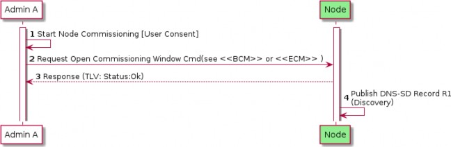
Figure 32. Open Commissioning Window (Administrator A)
Device Commissioning Flows
This section describes the three different flows for out-of-box commissioning that a Matter device manufacturer may select for a given product. For each flow, a description is provided which includes actions required to place the device into commissioning mode, fields in the Onboarding Payload which identify the flow selected by the device manufacturer, fields in the Distributed Compliance Ledger that provide information used for commissioning and help the Commissioner provide the user with appropriate instructions, and requirements for device packaging relating to the Onboarding Payload. The three flows are the following:
Standard Commissioning Flow
User-Intent Commissioning Flow
Custom Commissioning Flow
Matter device manufacturers SHALL use the Distributed Compliance Ledger to provide commissioners with information and instructions for both initial and secondary commissioning, and SHOULD use this Ledger to provide links to the user guide, a link to a manufacturer app, and other pre-setup information, to enable an optimal commissioning flow without requiring bilateral arrangements between each commissioner manufacturer and each device manufacturer.
Some fields in the Ledger SHALL or SHOULD be populated, depending on the type of commissioning flow, as detailed in the text below and in the Distributed Compliance Ledger section.
Standard Commissioning Flow
A Standard Commissioning Flow device SHALL be available for initial commissioning by any Matter commissioner.
A Standard Commissioning Flow device, when in factory-new state, SHALL start advertising automatically upon power on (see Commencement).
A Standard Commissioning Flow device SHALL set Custom Flow bits in the Onboarding Payload to indicate '0 - Standard Flow'.
A Standard Commissioning Flow device SHALL follow the rules for Manual Pairing Code and QR Code Inclusion.
For the case where the device has stopped advertising (e.g. user has powered on the device longer ago than the advertisement period), the manufacturer SHOULD provide guidance about how to bring the device back into advertising mode using the CommissioningModeInitialStepsHint field from the Distributed Compliance Ledger. Commissioners SHOULD use this information to guide the user for this case.
When commissioning fails, the commissioner MAY also reference Distributed Compliance Ledger fields such as UserManualUrl, SupportUrl and ProductUrl to assist the user in further steps to resolve the issue(s).
The Distributed Compliance Ledger entries for Standard Commissioning Flow devices SHALL include the CommissioningCustomFlow field set to '0 - Standard' and the CommissioningModeInitialStepsHint field set to a non-zero integer value, with bit 0 (Power Cycle) being set to 1. The CommissioningModeInitialStepsInstruction field SHALL be set when CommissioningModeInitialStepsHint has a Pairing Instruction dependency.
Table 51. Values of Ledger fields to represent Standard Commissioning Flow
Field Name
Value(s)
CommissioningCustomFlow
0 - Standard (Mandatory)
CommissioningModeInitialStepsHint
This field SHALL be set to a non-zero integer value. See Pairing Hint Table for a complete list of pairing instructions.
Example value: 33 - The following bits are set: 0 (Power Cycle - Mandatory), 5 (Device Manual - Optional). Bit 1 (Device Manufacturer URL) MAY be set.
CommissioningModeInitialStepsInstruction
The field SHALL be set when CommissioningModeInitialStepsHint has a Pairing Instruction dependency. See PI Dependency column of Pairing Hint Table to determine which pairing hints have Pairing Instruction dependency and therefore require this field to be populated.
User-Intent Commissioning Flow
A User-Intent Commissioning Flow device SHALL be available for initial commissioning by any Matter commissioner.
A User-Intent Commissioning Flow device, when in factory-new state, SHALL NOT start advertising automatically upon application of power (see Commencement).
To place a User-Intent Commissioning Flow device into advertising mode, some form of user
interaction with the device beyond application of power is required (see Pairing Hint Table). If a Device Manufacturer setup artifact is required for this, beyond documentation, then the device is a Custom Commissioning Flow device and not a User-Intent Commissioning Flow device. The documentation MAY be printed or in the form of online documentation (e.g. Section 11.23.5.8, “UserManualUrl”).
A User-Intent Commissioning Flow device SHALL follow the rules for Manual Pairing Code and QR Code Inclusion.
The Distributed Compliance Ledger entries for User-Intent Commissioning Flow devices SHALL include the CommissioningCustomFlow field set to '1 - User Intent' and the CommissioningModeInitialStepsHint field set to a non-zero integer value. Bit 0 (Power Cycle) in the CommissioningModeInitialStepsHint field SHALL be set to 0. The CommissioningModeInitialStepsInstruction field SHALL be set when CommissioningModeInitialStepsHint has a Pairing Instruction dependency.
A User-Intent Commissioning Flow device SHALL set Custom Flow bits in the Onboarding Payload to indicate '1 - User Intent'.
The commissioner SHOULD reference Distributed Compliance Ledger fields such as CommissioningModeInitialStepsHint, CommissioningModeInitialStepsInstruction, UserManualUrl, and SupportUrl to assist the user during commissioning, e.g. to explain how to bring the device into commissioning mode.
Table 52. Values of Ledger fields to represent User-Intent Commissioning Flow
Field Name
Value(s)
CommissioningCustomFlow
1 - User Intent (Mandatory)
CommissioningModeInitialStepsHint
This field SHALL be set to a non-zero integer value. See Pairing Hint Table for a complete list of pairing instructions.
Example value: 96 - The following bits are set: 6 (Press Reset Button - Optional), 5 (Device Manual - Optional). Bit 1 (Device Manufacturer URL) MAY be set.
CommissioningModeInitialStepsInstruction
The field SHALL be set when CommissioningModeInitialStepsHint has a Pairing Instruction dependency. See PI Dependency column of Pairing Hint Table to determine which pairing hints have Pairing Instruction dependency and therefore require this field to be populated.
Custom Commissioning Flow
A Custom Commissioning Flow device SHALL require interaction with custom steps, guided by a service provided by the manufacturer for initial device setup, before it can be commissioned by any Matter commissioner.
A Custom Commissioning Flow device MAY include the Onboarding Payload on-device or in packaging. If it is not included on the device or in packaging, then it SHALL be provided to the user through other means provided by the manufacturer.
A Custom Commissioning Flow device SHALL set Custom Flow bits in the Onboarding Payload to indicate '2 - Custom'.
The Distributed Compliance Ledger entries for Custom Commissioning Flow devices SHALL include:
the CommissioningCustomFlow field set to '2 - Custom'
the CommissioningModeInitialStepsHint with bit 0 (Power Cycle) set to 0 and bit 1 (Device Manufacturer URL) set to 1
the CommissioningCustomFlowUrl field populated in order to indicate to commissioners that initial commissioning can only be completed by the user visiting the URL contained therein.
This URL will typically lead to a web page with relevant instructions and/or to a server which (e.g. by looking at the User-Agent) redirects the user to allow viewing, downloading, installing or using a manufacturer-provided means for guiding the user through the process and bring the device into a state that it is available for commissioning by any commissioner. Since the URL is retrieved from a DCL entry corresponding to a specific VID and PID combination, the device manufacturer MAY choose to use any constructed URL valid in a HTTP GET request (i.e. dedicated for the product the user wants to commission) such as, for example, https://www.example.com/download-install-app?vid=FFF1&pid=1234. All HTTP based URLs SHALL use the https scheme.
When a Commissioner encounters a device with Custom Flow field (in Onboarding Payload) or its CommissioningCustomFlow field (in Distributed Compliance Ledger) set to '2 - Custom', it SHOULD use the CommissioningCustomFlowUrl to guide the user on how to proceed, unless it has alternative means to guide the user to successful commissioning.
If a Commissioner follows or launches the CommissioningCustomFlowUrl after a User request, it SHALL expand it as described in Section 5.7.3.1, “CommissioningCustomFlowUrl format”.
A manufacturer contemplating using this flow should realize that
This flow typically requires internet access to access the URL, so initial commissioning of the device may fail if there is no internet connection at that time/location.
If the flow requires an app, it needs to be made available for popular platforms amongst the user population; some of their platforms running a commissioner (e.g. a smart speaker not running a popular mobile OS) may thus not be able to be used for the initial commissioning of such devices.
Table 53. Values of Ledger fields to represent Custom Commissioning Flow
Field Name
Value(s)
CommissioningCustomFlow
2 - Custom (Mandatory)
CommissioningCustomFlowUrl
'URL' - Device Manufacturer URL (Mandatory)
Field Name
Value(s)
CommissioningModeInitialStepsHint
This field SHALL be set to a non-zero integer value with at least bit 1 set (Device Manufacturer URL). See Pairing Hint Table for a complete list of pairing instructions.
Example value: 2 - The following bits are set: 1 (Device Manufacturer URL) (Mandatory).
CommissioningModeInitialStepsInstruction
The field SHALL be set when CommissioningModeInitialStepsHint has a Pairing Instruction dependency. See PI Dependency column of Pairing Hint Table to determine which pairing hints have Pairing Instruction dependency and therefore require this field to be populated.
CommissioningCustomFlowUrl format
The CommissioningCustomFlowUrl MAY contain a query component (see RFC 3986 section 3.4). If a query is present, it SHALL be composed of one or more key-value pairs:
The query SHALL use the & delimiter between key/value pairs.
The key-value pairs shall in the format name=<value> where name is the key name, and <value> is the contents of the value encoded with proper URL-encoded escaping.
If key MTcu is present, it SHALL have a value of "_" (i.e. MTcu=_). This is the "callback URL (CallbackUrl) placeholder".
If key MTop is present, it SHALL have a value of "_" (i.e. MTop=_). This is the "onboarding payload placeholder".
Any key whose name begins with MT not mentioned in the previous bullets SHALL be reserved for future use by this specification. Manufacturers SHALL NOT include query keys starting with MT in either the CommissioningCustomFlowUrl or CallbackUrl unless they are referenced by a version of this specification.
When the CommissioningCustomFlowUrl for a Custom Commissioning Flow device includes the MTop key, the Passcode embedded in any Onboarding Payload placed on-device or in packaging SHALL NOT be one that can be used for secure channel establishment with the device. This requirement is intended to ensure a shared secret used for proof of possession will not be transferred to a server without user consent. A Custom Commissioning Flow device MAY utilize Onboarding Payload fields such as the Serial Number (see kTag_SerialNumber) to pass device identification to the server specified in CommissioningCustomFlowUrl, as these fields by themselves could not be used to gain access to the device on their own like the Passcode could.
When the CommissioningCustomFlowUrl for a Custom Commissioning Flow device includes the MTop key, the Passcode embedded in any Onboarding Payload placed on-device or in packaging MAY be set to 0 in order to provide a hint to the Commissioner that it is not one that can be used for secure channel establishment with the device. This would allow the Commissioner to avoid attempting to
commission the device if an advertisement from it is detected.
Any other element in the CommissioningCustomFlowUrl query field not covered by the above rules, as well as the fragment field (if present), SHALL remain as obtained from the Distributed Compliance Ledger's CommissioningCustomFlowUrl field, including the order of query key/value pairs present.
Expansion of CommissioningCustomFlowUrl by Commissioner
Once the URL is obtained, it SHALL be expanded to form a final URL (ExpandedCommissioningCustomFlowUrl) by proceeding with the following substitution algorithm on the original CommissioningCustomFlowUrl:
If key MTcu is present, compute the CallbackUrl desired (see Section 5.7.3.2, “CallbackUrl format for Custom Commissioning Flow response”), and substitute the placeholder value "_" (i.e. in MTcu=_) in the CommissioningCustomFlowUrl with the desired contents, encoded with proper URL- encoded escaping (see RFC 3986 section 2).
If key MTop is present, substitute the the placeholder value "_" (i.e. in MTop=_) in the CommissioningCustomFlowUrl with either numeric manual code, or QR code body including the MT: prefix and TLV data (if present), encoded with proper URL-encoded escaping (see RFC 3986 section 2). Note that both methods SHOULD be supported by the Manufacturer’s custom flow.
A Commissioner SHALL NOT append the MTop= query key/value pair unless the key/value pair was already present as MTop=_ in the CommissioningCustomFlowUrl previously obtained. This constraint enables the determination of which products make use of the payload in their Custom Commissioning Flow infrastructure by inspection of the Distributed Compliance Ledger records.
The final URL after expansion (ExpandedCommissioningCustomFlowUrl) SHALL be the one to follow per Section 5.7.3, “Custom Commissioning Flow”, rather than the original value obtained from the Distributed Compliance Ledger.
CallbackUrl format for Custom Commissioning Flow response
If a CallbackUrl field (i.e. MTcu=) query field placeholder is present in the CommissioningCustomFlowUrl, the Commissioner MAY replace the placeholder value "_" in the ExpandedCommissioningCustomFlowUrl with a URL that the manufacturer custom flow can use to make a smooth return to the Commissioner when the device is in a state that it can be commissioned.
This URL field MAY contain a query component (see RFC 3986 section 3.4). If a query is present, it SHALL be composed of one or more key-value pairs:
The query SHALL use the & delimiter between key/value pairs.
The key-value pairs SHALL follow the format name=<value> where name is the key name, and
<value> is the contents of the value encoded with proper URL-encoded escaping.
If key MTrop is present, it SHALL have a value of "_" (i.e. MTrop=_). This is the placeholder for a "returned onboarding payload" provided by the manufacturer flow to the Commissioner.
Any key whose name begins with MT not mentioned in the previous bullets SHALL be reserved for future use by this specification.
Any other element in the CallbackUrl query field not covered by the above rules, as well as the fragment field (if present), SHALL remain as provided by the Commissioner through embedding within the ExpandedCommissioningCustomFlowUrl, including the order of query key/value pairs present.
Expansion of CallbackUrl by the manufacturer custom flow
Once the CallbackUrl is obtained by the manufacturer flow, it MAY be expanded to form a final ExpandedCallbackUrl URL to be used by proceeding with the following substitution algorithm on the provided CallbackUrl:
If key MTrop is present, the manufacturer custom flow having received the initial query containing the CallbackUrl MAY compute an Onboarding Payload in QR code format including MT: prefix, and substitute the placeholder value "_" (i.e. in MTrop=_) in the CallbackUrl with the desired contents, encoded with proper URL-encoded escaping (see RFC 3986 section 2).
The contents of the MTrop=_ key/value pair in the ExpandedCallbackUrl SHALL only be expanded if the manufacturer custom flow, having received the initial query containing the CallbackUrl, supports opening a commissioning window on the target device and supports conveying the corresponding onboarding payload to the Commissioner.
The return onboarding payload, if provided, SHALL contain an ephemeral Passcode and not a permanent code that can be used in a subsequent commissioning window. If the manufacturer wants the Passcode embedded in the Onboarding Payload placed on-device or in packaging to be the one used for session establishment with the Commissioner, then the manufacturer SHALL NOT include the MTop key in its CommissioningCustomFlowUrl and SHALL NOT populate the MTrop value in the CallbackUrl expansion.
The contents of the return onboarding payload, if provided, SHALL be constructed to match the state of the device at the moment the ExpandedCallbackUrl is opened. At least one ingredient which needs to be adapted relative to the received Onboarding Payload is the Custom Flow field which needs to be 0 for the return onboarding payload.
The presence of this field is to assist automatically resuming commissioning without additional data entry (QR code or numeric manual code) by the user at the Commissioner that initially triggered the custom flow. The manufacturer custom flow SHOULD provide an alternate means of conveying the onboarding payload, such as a manual pairing code.
Note that if the information in the initial onboarding payload that caused triggering of a Custom Commissioning Flow was directly usable, it may be used by the Commissioner, either upon being triggered through the ExpandedCallbackUrl having been opened, or autonomously as a fallback.
Commissioners providing a CallbackUrl to the manufacturer custom flow through the ExpandedCommissioningCustomFlowUrl SHOULD support using the ExpandedCallbackUrl to trigger resumption of Commissioning flow if the ExpandedCallbackUrl is followed, otherwise the Commissioner SHOULD NOT substitute the MTcu query field when expanding the CommissioningCustomFlowUrl into the ExpandedCommissioningCustomFlowUrl.
If the manufacturer custom flow failed to make the device commissionable, it SHALL NOT replace the placeholder value "_" of an included MTrop=_ key/value pair, to avoid a Commissioner attempting to discover or commission a device not made ready by the custom flow.
A manufacturer custom flow having received an ExpandedCommissioningCustomFlowUrl SHOULD attempt to open the ExpandedCallbackUrl, on completion of the steps, if an ExpandedCallbackUrl was computed from the CallbackUrl and opening such a URL is supported.
Examples of CommissioningCustomFlow URLs
Below are some examples of valid ExpandedCommissioningCustomFlowUrl for several valid values of CommissioningCustomFlowUrl, as well as some examples of invalid values of CommissioningCustomFlowUrl:
Valid URL with no query string:
Before expansion: https://company.example.com/matter/custom/flows/vFFF1p1234
After expansion: https://company.example.com/matter/custom/flows/vFFF1p1234 (no change)
Invalid URL with no query string: http scheme is not allowed:
Valid URL with basic manufacturer-specific scheme for query:
Before expansion: https://company.example.com/matter/custom/flows?vid=FFF1&pid=1234
After expansion: https://company.example.com/matter/custom/flows?vid=FFF1&pid=1234 (no change)
Valid URL with MTop=_ placeholder using QR format onboarding payload embedding:
Before expansion: https://company.example.com/matter/custom/flows?vid=FFF1&pid=1234& MTop=_
After expansion: https://company.example.com/matter/custom/flows?vid=FFF1&pid=1234& MTop=MT%3A-MOA57ZU02IT2L2BJ00
Onboarding payload QR content MT:-MOA57ZU02IT2L2BJ00 was embedded within MTop key
Valid URL with MTop=_ placeholder using numeric manual code onboarding payload embedding:
Before expansion: https://company.example.com/matter/custom/flows?vid=FFF1&pid=1234& MTop=_
After expansion: https://company.example.com/matter/custom/flows?vid=FFF1&pid=1234& MTop=610403146665521046600
Onboarding numeric manual code 610403146665521046600 was embedded within MTop key
Valid URL with MTop=_ placeholder using numeric manual code onboarding payload embedding, using a different order of keys/value pairs than the previous example:
Before expansion: https://company.example.com/matter/custom/flows?pid=1234&MTop=_& vid=FFF1
After expansion: https://company.example.com/matter/custom/flows?pid=1234& MTop=610403146665521046600&vid=FFF1
Onboarding numeric manual code 610403146665521046600 was embedded within MTop key
Valid URL with onboarding payload elided (because commissioner could not provide it):
Valid URL, return onboarding payload and CallbackUrl requested:

https://company.example.com/matter/custom/flows?vid=FFF1&pid=1234&MTop=_&MTcu=_
Before expansion:

https://company.example.com/matter/custom/flows?vid=FFF1&pid=1234&MTop=MT%3A- MOA57ZU02IT2L2BJ00&MTcu=https%3A%2F%2Fcommissioner.example.com%2Fcb%3Ftoken%3DmA sJ6_vqbr-vjDiG_w%253D%253D%26MTrop%3D_
After expansion:
The ExpandedCommissioningCustomFlow URL contains:
An embedded onboarding payload QR content value of MT:-MOA57ZU02IT2L2BJ00
A CallbackUrl with a Commissioner-provided arbitrary token= key/value pair and the MTrop= key/value pair place-holder to indicate support for a return onboarding payload: https://commissioner.example.com/cb?token=mAsJ6_vqbr-vjDiG_w%3D%3D&MTrop=_

https://commissioner.example.com/cb?token=mAsJ6_vqbr- vjDiG_w%3D%3D&MTrop=MT%3A-MOA5.GB00V68T62O10
After expansion of the CallbackUrl (MTcu key) into an ExpandedCallbackUrl, with an example return onboarding payload of MT:-MOA5.GB00V68T62O10, the ExpandedCallbackUrl would be:
Note that the MTcu key/value pair was initially provided URL-encoded within the ExpandedCommissioningCustomFlow URL and the MTrop=_ key/value pair placeholder now contains a substituted returned onboarding payload.
Invalid URL, due to MTza=79 key/value pair in reserved MT-prefixed keys reserved for future use:
Example Custom Commissioning Flow
An example of this flow is illustrated below. The "DCL info" concept denotes that the Commissioner SHALL collect the information from the DCL via some mechanism, such as a network resource accessible to the Commissioner containing a replicated set of the DCL’s content.
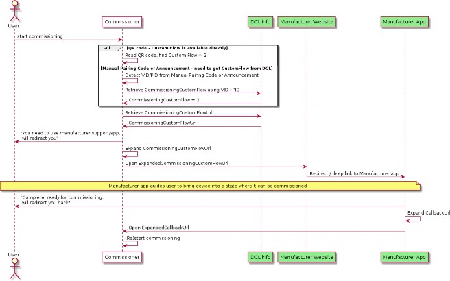
Figure 33. Custom Commissioning Flow sequence diagram
In the flow above:
In the final steps, the User has to perform the trigger to the first Commissioner, so that it can start or continue the commissioning process.
If possible, a Commissioner MAY continue to scan for announcements from the device in the background while any manufacturer-specific app is configuring the device to be available for commissioning. The Commissioner may need a new OnboardingPayload provided to the User by the Manufacturer Website or App.
In order to simplify the flow, the Commissioner MAY:
Include the onboarding payload obtained from the user (see MTop key in Section 5.7.3.1, “CommissioningCustomFlowUrl format”) within the CommissioningCustomFlowUrl.
Include a callback URL (see MTcu key in Section 5.7.3.1, “CommissioningCustomFlowUrl format”) within the ExpandedCommissioningCustomFlowUrl.
The Manufacturer Website or App MAY utilize the CallbackUrl field, if provided in the query string, in order to simplify the process for signaling the completion of the manufacturer-specific part of the flow back to the Commissioner. When doing so, the Manufacturer Website or App SHOULD put the device into Commissioning mode and SHOULD provide the corresponding onboarding payload to the Commissioner using the MTrop key/value pair within the ExpandedCallbackUrl.
Manual Pairing Code and QR Code Inclusion
Manual Pairing Code and QR setup codes enable secure commissioning and provide a consistent experience that many users are familiar with. However, because they contain a symmetric security
code it is not appropriate in all circumstances to have them be in a readily accessible location on the device, such as printed on the back.
The following are the requirements and recommendations regarding the QR Code and Manual Pairing code for Standard and User Intent Commissioning Flow Devices. Custom Commissioning Flow Device rules are described in the Custom Commissioning Flow.
The term 'on-device' allows for a physical label affixed to the device or printed directly on the device, as well as one that can be displayed on demand through some physical interface properties of the device (e.g. visual or audio).
Devices SHALL include the Manual Pairing code on-device or in packaging.
Devices SHALL NOT have the QR nor the manual pairing code in an unprotected format on the outer packaging.
Devices SHOULD include the QR Code, and SHOULD include it alongside the Manual Pairing Code on-device or in packaging.
Manual Pairing Code and QR Code on-device MAY be removable or obscured to allow the owner to prevent commissioning without their consent.
Devices MAY include the QR Code and Manual Pairing Code in multiple forms (see below).
Presentation of the QR Code and Manual Pairing code on-device can occur in many forms to allow for adherence to device security requirements and manufacturing considerations. For example security devices could limit the access to the QR code or Manual Pairing Code to avoid an unauthorized user obtaining the information by simple inspection, or make the QR code and/or Manual Pairing Code removable.
The following is a list of possible ways that are acceptable to satisfy the requirements of inclusion of the QR code and Manual Pairing Code. An entry in the list should not be interpreted as being mutually exclusive with another entry. A device SHOULD include as many of these ways as possible.
QR and Manual Pairing Code shown via an on-device display (when available)
QR and Manual Pairing Code printed on-device, with removal/obscuring considerations noted above.
Manual Pairing Code presented on-device via audio output (when available)
QR and Manual Pairing Code printed on in-packaging materials.
The following are examples of QR code and Manual Pairing Code inclusion.
QR Code and Manual Pairing Code printed on a Matter wireless shade inside the battery compartment cover, and provided in the packaging.
QR Code and Manual Pairing code on a Matter Smart Thermostat that can be activated via an on-device User Interface and displayed only on screen.
QR Code and Manual Pairing code for a security sensor that is provided in the packaging, and on-device hidden behind a tamper-monitored cover.
QR code provided on an E12 light bulb, with manual pairing code on a removable label (the area of QR code likely fits better on small form factor bulb than the area for a 13 character
string).
A wearable device with only a Manual Pairing Code printed on the fabric. No QR code is present because of the difficulty in scanning a QR code on an irregular surface.
A Smart speaker, without printed QR or manual pairing code on the device (but possibly in- packaging), that can be triggered to read out a Manual Pairing Code.
In-field Upgrade to Matter