Practical Information
Revision History
Revision
Description
1
Initial Release of this specification
Scope and Purpose
This is part of a package of Data Model specifications that are agnostic to underlying layers (encoding, message, network, transport, etc.). Each specification below may be independently maintained. This package, as a whole, shall be independently maintained as agnostic and decoupled from lower layers. This package may be referenced by inclusion in a set of protocol stack specifications for a complete vertical standard.
Data Model Defines first order elements and namespace for endpoints, clusters, attributes, data types, etc.
Interaction Model Defines interactions, transactions and actions between nodes.
System Model Defines relationships that are managed between endpoints and clusters.
Cluster Library Reference library of cluster specifications.
Device Library Reference library of devices type definitions.
Origin Story
The origin of this section is the Dotdot Architecture Model and parts of Chapter 2 of the Zigbee Cluster Library specification that define the data model.
The purpose is that this document will align with current cluster specifications in the ZCL and still support cluster updates and evolution into a single set of data models.
Overview
This specification defines persistent relationships between local and remote instances of data model elements, that support a system of operational communication between such instances. A system is a set of nodes and persistent relationships that automate data flow and control based on local or external stimulus.
Endpoint Composition
Endpoint composition SHALL be indicated by these Descriptor cluster attributes:
DeviceTypeList SHALL list the device type(s) that the endpoint supports
PartsList SHALL indicate the endpoints that support these device type(s)
Each simple endpoint SHALL support only one Application device type with these exceptions:
The endpoint MAY support additional device types which are subsets of the Application device type (the superset).

For Example: A Color Temperature Light device type may support device type IDs for both a Dimmable Light and On/Off Light, because those are subsets of a Color Temperature Light (the superset).
For Example: A Room Temperature Sensor device type and a Room Humidity Sensor device type must be on separate endpoints because they are both Simple device types and neither is a subset of the other.
For example: The Bridged Node device type may be added to an endpoint, which means it represents a node behind a bridge, and requires one or more extra clusters.
The endpoint MAY support additional device types (application, utility or node device types) as defined by each additional device type.

For example: The Temperature Sensor device type mandates the Temperature Measurement server cluster, and does not require additional device types or endpoints.
A leaf device type is not composed of other device types.

For example: A Dimmer Switch device type mandates these clusters: On/Off, Level Control, Identify, and does not require additional device types or endpoints.
Most device types define leaf endpoints without the need for composition.
A composed device type is composed of two or more other device types.

For example: An endpoint supporting a Freezer device type which has 2 temperature sensors (freezer temperature, and ice tray temperature) would have a PartsList containing 2 temperature sensor leaf endpoints (one for each of the sensors). Those leaf endpoints would indicate and conform to the temperature sensor device type.
A composed device type MAY indicate a PartsList of local endpoints that are part of the composed device type.
A root node device type SHALL be a singleton on the root node endpoint.
The PartsList of the Descriptor cluster on the root node endpoint SHALL list all endpoints on the node, except the root node endpoint.
The root node endpoint SHALL NOT exist in any other endpoint’s PartsList on the node.
The root node endpoint requirements are defined by a node scoped device type.
There SHALL be only one root node endpoint for the node.
Each device type that is part of a composed device type indicated in the Descriptor cluster DeviceTypeList attribute, SHALL each be supported by an endpoint in the PartsList.
Each endpoint that supports a device type that is a conformant part of a composed device type on another endpoint SHALL be indicated, along with endpoints in its own PartsList, in the PartsList of the composed device type endpoint.

For example: A Fridge/Freezer endpoint has a PartsList with the Fridge and Freezer endpoint, but also all other dependent endpoints below, including temperature sensor endpoints for the Fridge, Freezer, and Ice Tray (which is part of the Freezer), etc.
This means that each PartsList indicates all endpoints below it, in the tree hierarchy of composed device types.
Extra endpoints MAY be in the PartsList that extend the device type implementation.
Dynamic Endpoint allocation
Some nodes MAY require a dynamic number of endpoints, since the functionality they expose can change at run-time, e.g.
a Bridge on which Bridged Devices are added or deleted.
a Casting Video Player in which Content Apps are added or deleted (see Device Library, section 10).
Such dynamic entities which need to be exposed with an endpoint, will be referred to as an "exposed entity" in the following description.
For such nodes with dynamic endpoints, the endpoint addresses SHALL be allocated according to the following rules:
When such exposed entity is exposed for the first time, it SHALL be allocated a new endpoint address (or set of endpoint addresses), incrementing from the highest previously (ever) used endpoint address.
For the situation where a node following these mechanisms has exhausted all available 65535 endpoint addresses for exposed entities, it MAY wrap around to the lowest unused endpoint address.
For existing exposed entities, the endpoint addresses SHALL NOT be changed.
This persistency requirement also holds for the case of restart/reboot of the device.
As a result of these mechanisms, endpoint addresses that were used for exposed entities that were once exposed but now have been removed will not be reused in the future (apart from the exceptional wrap-around corner case mentioned above), in order to avoid the possibility of confusing other nodes by re-assigning (reusing) an endpoint address for a different exposed entity. Other nodes using the exposed entities from this node SHOULD remove information related to exposed entities no longer being exposed.
Other nodes that wish to be notified of changes of the exposed entities SHOULD monitor changes of the PartsList attribute in the Descriptor cluster on the root node endpoint.
Interaction Model Relationships
This section define some of the system behaviors and their constraints as they apply to interactions specified in the Interaction Model.
Subscription
Persistency
A subscription is an ephemeral 'session' between a subscriber and a publisher. A subscription can lose synchronization for a variety of reasons, including (but not limited to):
Inability to send reports due to network connectivity issues
Factory-reset of the publisher
Reboot of either the subscriber or publisher
Decision by either publisher or subscriber to tear down the subscription to reclaim resources
In all cases, the subscriber can eventually discover the loss of synchronization by not receiving a sync report or data report in the agreed upon sync interval, or through some other failure to communicate with the publisher.
When a subscriber discovers the loss of synchronization, it MAY then initiate a re-subscription to resume the subscription.
An implementation MAY choose to persist the details of a subscription across reboots, but it is not necessary.
In all cases, the publisher eventually discovers the loss of synchronization by not receiving a Status Response to a Report Data message that expects a response, or by receiving an error Status Response.
Binding Relationship
This relationship occurs because a simple client endpoint does not know which endpoints will be the target for the client generated actions, on one or more remote nodes.

For example: A light switch that controls one or more light bulbs, does not know the remote node endpoints of the bulbs.
For example: A thermostat that subscribes to an occupancy sensor, does not know the remote node endpoint of the sensor.
In such cases, a binding is used to direct the local endpoint to the remote endpoint. The existence of the Binding cluster on an endpoint, allows a director to create one or more binding entries (bindings) in the Binding cluster. A director is a remote client that is given access to create such bindings.
Each binding indicates either a remote node’s endpoint or cluster on a remote node’s endpoint. Multiple bindings are allowed, depending on the interaction. A binding is either a unicast binding, where the binding target is a remote endpoint, or a groupcast binding, where the binding target is a group of remote endpoints.
Please see the Binding Cluster specification for more specification detail.
Descriptor Cluster

NOTE The Descriptor cluster is meant to replace the support from the Zigbee Device Object (ZDO) for describing a node, its endpoints and clusters.
This cluster describes an endpoint instance on the node, independently from other endpoints, but also allows composition of endpoints to conform to complex device type patterns.

For Example: An Extended Color Light device type may support device type IDs for both a Dimmable Light and On/Off Light, because those are subsets of an Extended Color Light (the superset).
This cluster supports a list of one or more device type identifiers that represent conformance to device type specifications.

For Example: A Refrigerator/Freezer appliance device type may be defined as being composed of multiple Temperature Sensor endpoints, a Metering endpoint, and two Thermostat endpoints.
The cluster supports a PartsList attribute that is a list of zero or more endpoints to support a composed device type.
Revision History
The global ClusterRevision attribute value SHALL be the highest revision number in the table below.
Revision
Description
1
Initial Release
Classification
Hierarchy
Role
Context
PICS Code
Base
Utility
Endpoint
DESC
Cluster Identifiers
Identifier
Name
0x001D
Descriptor
Attributes
Id
Name
Type
Quality
Constraint
Default
Access
Conforma nce
0x0000
DeviceTyp eList
list[Device TypeStruct
]
F
min 1
desc
R V
M
0x0001
ServerList
list[cluster- id]
F
empty
R V
M
0x0002
ClientList
list[cluster- id]
F
empty
R V
M
0x0003
PartsList
list[endpoi nt-no]
empty
R V
M
DeviceTypeList Attribute
This is a list of device types and corresponding revisions declaring endpoint conformance (see DeviceTypeStruct). At least one device type entry SHALL be present.
An endpoint SHALL conform to all device types listed in the DeviceTypeList. A cluster instance that is in common for more than one device type in the DeviceTypeList SHALL be supported as a shared cluster instance on the endpoint.
See the System Model specification for endpoint composition.
ServerList Attribute
This attribute SHALL list each cluster ID for the server clusters present on the endpoint instance.
ClientList Attribute
This attribute SHALL list each cluster ID for the client clusters present on the endpoint instance.
PartsList Attribute
This attribute indicates composition of the device type instance. Device type instance composition SHALL include the endpoints in this list. See Endpoint Composition for more information.
Data Types
9.5.5.1. DeviceTypeStruct
The device type and revision define endpoint conformance to a release of a device type definition. See the Data Model specification for more information.
Table 74. DeviceTypeStruct
ID
Name
Type
Quality
Constraint
Access
Conformanc e
0
DeviceType
devtype-id
M
1
Revision
uint16
min 1
M
DeviceType Field
This SHALL indicate the device type definition. The endpoint SHALL conform to the device type definition and cluster specifications required by the device type.
Revision Field
This is the implemented revision of the device type definition. The endpoint SHALL conform to this revision of the device type.
Binding Cluster

NOTE
This scope of this document is the Binding cluster as part of the Cluster Library. The Binding cluster is meant to replace the support from the Zigbee Device Object (ZDO) for supporting the binding table.
A binding represents a persistent relationship between an endpoint and one or more other local or remote endpoints. A binding does not require that the relationship exists. It is up to the node application to set up the relationship.
A binding is used to inform a client endpoint of one or more targets for a potential interaction. For example: a light switch that controls one or more light bulbs, needs to be told the nodes and endpoints of the bulbs, or told a group in which the bulbs are members. For example: A client that needs to subscribe to an occupancy sensor, needs to know the node and endpoint of the sensor.
In such cases, a binding is used to direct a local endpoint to a target. The existence of the Binding cluster on the client endpoint, allows the creation of one or more binding entries (bindings) in the Binding cluster.
Each binding indicates another endpoint or cluster on another endpoint. Multiple bindings are
allowed, depending on the interaction.
A binding is either a unicast binding, where the target is a single endpoint on a single node, or a groupcast binding, where the target is a group, which may indicate multiple endpoints on multiple nodes. The binding may also target a single cluster on the target endpoint(s).
When a client cluster requires a target for an interaction, the Binding cluster SHALL exist on the same endpoint.
Once a binding entry is created on the Binding cluster, the client endpoint MAY initiate interactions to the binding target.
Binding Mutation
If, during the creation of multiple bindings, there are no available resources to create an entry, or to establish a binding relationship, the client SHALL respond with a status of RESOURCE_EXHAUSTED, and the binding SHALL NOT be created.
The number of bindings supported is left to the implementation. However, a device type definition MAY prescribe the minimum number of bindings supported on an endpoint. In this case, the number prescribed by the device type SHALL be supported for each fabric the node supports, unless the device type specifies otherwise. The total number of bindings supported SHALL be the sum of the requirements for each endpoint, unless the device types involved specify otherwise.
For example, if a node supports 6 fabrics and a device type specifies at least 3 bindings must be supported, the node would need to support at least 18 bindings and ensure that at least 3 were available to every fabric.
A binding SHALL only be created with the Cluster field if the indicated client cluster exists on the endpoint.
When a binding is removed, the client endpoint SHALL end the binding relationship with the removed binding target.
Revision History
The global ClusterRevision attribute value SHALL be the highest revision number in the table below.
Revision
Description
1
Initial Release
Classification
Hierarchy
Role
Scope
PICS Code
Base
Utility
Endpoint
BIND
Cluster Identifiers
Identifier
Name
0x001E
Binding
Attributes
Id
Name
Type
Quality
Constraint
Access
Default
Conforma nce
0x0000
Binding
list[TargetS truct]
N
desc
RW F VM
[]
M
9.6.5.1. Binding Attribute
Endpoint Device Type
Node
Group
Cluster
Endpoint
Example Description
Light Switch Client
omit
1234
omit
omit
switch endpoint sends On/Off, Level & Color Control cluster commands to group 1234
Temp Sensor Client
456789
omit
1026
3
temperature sensor client subscribes to node 456789
endpoint 3 temperature measurement
cluster
Each entry SHALL represent a binding. Here are some examples:
Data Types
9.6.6.1. TargetStruct
Access Quality: Fabric Scoped
ID
Name
Type
Quality
Constraint
Access
Default
Conforman ce
1
Node
node-id
all
Endpoint
2
Group
group-id
all
!Endpoint
Access Quality: Fabric Scoped
3
Endpoint
endpoint- no
all
!Group
4
Cluster
cluster-id
all
O
Node Field
This is the remote target node ID. If the Endpoint field is present, this field SHALL be present.
Group Field
This is the target group ID that represents remote endpoints. If the Endpoint field is present, this field SHALL NOT be present.
Endpoint Field
This is the remote endpoint that the local endpoint is bound to. If the Group field is present, this field SHALL NOT be present.
Cluster Field
This is the cluster ID (client & server) on the local and target endpoint(s). If this field is present, the client cluster SHALL also exist on this endpoint (with this Binding cluster). If this field is present, the target SHALL be this cluster on the target endpoint(s).
Label Cluster
This cluster provides a feature to tag an endpoint with zero or more labels. This is a base cluster that requires a derived cluster to create an instance.
Revision History
The global ClusterRevision attribute value SHALL be the highest revision number in the table below.
Revision
Description
1
Initial Release
Classification
Hierarchy
Role
Context
PICS Code
Base
Utility
Endpoint
LABEL
Cluster Identifiers
This is a base cluster with no cluster ID. Please see derived clusters for more information.
Identifier
Name
n/a
Label
Attributes
Id
Name
Type
Constraint
Quality
Default
Access
Conforma nce
0x0000
LabelList
list[LabelSt ruct]
derived
derived
empty
derived
M
9.7.4.1. LabelList Attribute
This is a list of string tuples. Each entry is a LabelStruct.
Data Types
9.7.5.1. LabelStruct
This is a string tuple with strings that are user defined.
Id
Name
Type
Constraint
Quality
Default
Access
Conforma nce
0
Label
string
max 16
empty
M
1
Value
string
max 16
empty
M
Label Field
The Label or Value semantic is not defined here. Label examples: "room", "zone", "group", "direction".
Value Field
The Label or Value semantic is not defined here. The Value is a discriminator for a Label that may have multiple instances. Label:Value examples: "room":"bedroom 2", "orientation":"North", "floor":"2", "direction":"up"
Fixed Label Cluster
This cluster provides a feature for the device to tag an endpoint with zero or more read only labels. Examples:
A bridge can use this to indicate grouping of bridged devices. For example: All bridged devices whose endpoints have an entry in their LabelList "room":"bedroom 2" are in the same (bed)room.
A manufacturer can use this to identify a characteristic of an endpoint. For example to identify the endpoints of a luminaire, one pointing up, the other pointing down, one of the endpoints
would have a LabelList entry "orientation":"up" while the other would have "orientation":"down". Using such indication, the user interface of a Node controlling this luminaire knows which of the endpoints is which of the lights.
Revision History
The global ClusterRevision attribute value SHALL be the highest revision number in the table below.
Revision
Description
1
Initial Release
Classification
Hierarchy
Role
Context
PICS Code
Derived from Label
Utility
Endpoint
FLABEL
Cluster Identifiers
Identifier
Name
0x0040
Fixed Label
Attributes
Name
Constraint
Quality
Default
Access
Conformance
LabelList
N
empty
R V
M
User Label Cluster
This cluster provides a feature to tag an endpoint with zero or more labels.
Revision History
The global ClusterRevision attribute value SHALL be the highest revision number in the table below.
Revision
Description
1
Initial Release
Classification
Hierarchy
Role
Context
PICS Code
Derived from Label
Utility
Endpoint
ULABEL
Cluster Identifiers
Identifier
Name
0x0041
User Label
Attributes
Name
Constraint
Quality
Default
Access
Conformance
LabelList
min 4 per node
N
empty
RW VM
M
9.9.4.1. LabelList
An implementation SHALL support at least 4 list entries per node for all User Label cluster instances on the node.
Access Control Cluster
The Access Control Cluster exposes a data model view of a Node’s Access Control List (ACL), which codifies the rules used to manage and enforce Access Control for the Node’s endpoints and their associated cluster instances. Access to this Access Control Cluster itself requires a special Administer privilege level, such that only Nodes granted such privilege (hereafter termed "Administrators") can manage the Access Control Cluster.
The Access Control Cluster SHALL be present on the root node endpoint of each Node, and SHALL NOT be present on any other Endpoint of any Node.
Revision History
The global ClusterRevision attribute value SHALL be the highest revision number in the table below.
Rev isio n
Description
1
Initial Release
Classification
Hierarchy
Role
Context
PICS Code
Base
Utility
Node
ACL
Cluster Identifiers
Ident ifier
Name
0x001 F
AccessControl
Features
This Cluster has no Features.
Attributes
Table 75. Access Control Cluster Server Attributes
ID
Name
Type
Constraint
Quality
Default
Access
Conforma nce
0x0000
ACL
list[Access ControlEnt ryStruct]
desc
desc
RW F A
M
0x0001
Extension
list[Access ControlExt ensionStru ct]
desc
desc
RW F A
O
0x0002
SubjectsPe rAccessCon trolEntry
uint16
min 4
F
4
R V
M
0x0003
TargetsPer AccessCont rolEntry
uint16
min 3
F
3
R V
M
0x0004
AccessCont rolEntriesP erFabric
uint16
min 3
F
3
R V
M
Default Value
The default value of the Access Control Cluster is empty; that is, devoid of contents, with each list attribute containing zero elements.
The Access Control List is able to have an initial entry added because the Access Control Privilege Granting algorithm behaves as if, over a PASE commissioning channel during the commissioning phase, the following implicit Access Control Entry were present on the Commissionee (but not on the Commissioner):

// entire node
// implicit entry only; does not explicitly exist!
// not fabric-specific
Access Control Cluster: { ACL: [
0: {
FabricIndex: 0, Privilege: Administer, AuthMode: PASE, Subjects: [],
Targets: []
}
],
Extension: []
}
Administration Guidelines
The Access Control Cluster is passive in nature and is only responsible for maintaining entries in the Access Control List. It is the responsibility of Administrators to create and maintain Access Control policy by managing the list and its entries. The Access Control Cluster SHALL NOT change or remove Access Control Entries of its own volition.
Administrators SHOULD strive to minimize resource usage by combining entries where appropriate. For example, if an Administrator is responsible for an entry that grants privilege to subject Node A, and wishes to grant the same privilege to Node B under the same conditions, then that Administrator SHOULD update the existing entry to apply to subject Node B as well as Node A, instead of creating a new entry. If a set of Nodes is commonly used in entries, then an Administrator MAY consider using CASE Authenticated Tags (CATs) for those entries, especially if membership in the set of Nodes changes over time.
Administrators SHOULD carefully consider the effect of Access Control Entries they manage, particularly when targeting entire Endpoints (either directly, or indirectly by Device Type), to ensure that granted privileges are appropriate for the set of Clusters that may entail. Administrators SHOULD be mindful that targeting by Device Type grants privileges to all Clusters on all Endpoints with Descriptor containing that Device Type (thereby including Clusters not part of that specified Device Type), now and in the future. Administrators SHOULD consider whether targeting specific Endpoints, or Clusters, or both, might be a more appropriate policy for the given Subjects; studying the Descriptor Cluster for affected Endpoints may help in this determination.
Administrators SHOULD be careful to avoid inadvertently removing their own administrative access. For example, an Administrator SHOULD change its own administrative access entry by updating the existing entry or by creating a new entry before removing the old entry, and SHOULD NOT remove the old entry before creating any new entry.
ACL Attribute
An attempt to add an Access Control Entry when no more entries are available SHALL result in a RESOURCE_EXHAUSTED error being reported and the ACL attribute SHALL NOT have the entry added to it. See access control limits.
See the AccessControlEntriesPerFabric attribute for the actual value of the number of entries per
fabric supported by the server.
Each Access Control Entry codifies a single grant of privilege on this Node, and is used by the Access Control Privilege Granting algorithm to determine if a subject has privilege to interact with targets on the Node.
Table 76. AccessControlEntryStruct
Access Quality: Fabric Scoped
ID
Name
Type
Constraint
Quality
Access
Default
Conforman ce
1
Privilege
AccessCont rolEntryPri vilegeEnu m
all
S
M
2
AuthMode
AccessCont rolEntryAu thModeEn um
all
S
M
3
Subjects
list[Subject ID]
max SubjectsPe rAccessCon trolEntry
X
S
M
4
Targets
list[TargetS truct]
max TargetsPer AccessCont rolEntry
X
S
M
Privilege
The privilege field SHALL specify the level of privilege granted by this Access Control Entry.
Table 77. PrivilegeEnum
Value
Name
Description
Implicitly Granted Privileges
1
View
Can read and observe all (except Access Control Cluster and as seen by a non-Proxy)
-
2
Proxy View
Can read and observe all (as seen by a Proxy)
View
3
Operate
View privileges, and can perform the primary function of this Node (except Access Control Cluster)
View
Value
Name
Description
Implicitly Granted Privileges
4
Manage
Operate privileges, and can modify persistent configuration of this Node (except Access Control Cluster)
Operate, View
5
Administer
Manage privileges, and can observe and modify the Access Control Cluster
Manage, Operate, Proxy View, View
Each privilege builds upon its predecessor, expanding the set of actions that can be performed upon a Node. Administer is the highest privilege, and is special as it pertains to the administration of privileges itself, via the Access Control Cluster.
When a Node is granted a particular privilege, it is also implicitly granted all logically lower privilege levels as well. The following diagram illustrates how the higher privilege levels subsume the lower privilege levels:
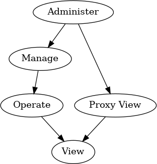
Figure 39. Access Control Privilege Levels
Individual clusters SHALL define whether attributes are readable, writable, or both readable and writable. Clusters also SHALL define which privilege is minimally required to be able to perform a particular read or write action on those attributes, or invoke particular commands. Device type specifications MAY further restrict the privilege required.
The Access Control Cluster SHALL require the Administer privilege to observe and modify the Access Control Cluster itself. The Administer privilege SHALL NOT be used on Access Control Entries which use the Group auth mode.

E.g. A Fan Control Cluster may require Operate privilege to write to a level attribute (low/medium/high), and to configure each level’s RPM setting via a command. The Fan Control Cluster may also expose a current RPM attribute, which requires only View privilege to read. Clients granted Operate privilege will be able to both change the level, and configure each level’s RPM. Clients granted View privilege will be able to read the current RPM, but will not be granted sufficient privilege to change the level or configure each level’s RPM.

E.g. A Fan Control Cluster may be included in a more industrial device type. To ensure proper operation, this device type may restrict configuration of fan level RPM settings to require Manage privilege. Clients granted Manage privilege will have sufficient privilege to configure each level’s RPM; clients granted Operate privilege will not be able to perform such configuration, but will still be able to change the level. This additional restriction would apply only to the Fan Control Cluster as included in this particular device type; a client granted Operate privilege may still be able to perform configuration in Fan Control Clusters included in other device types on the same Node.
AuthMode
The AuthMode field SHALL specify the authentication mode required by this Access Control Entry.
Table 78. AuthModeEnum
Value
Name
Description
1
PASE
Passcode authenticated session
2
CASE
Certificate authenticated session
3
Group
Group authenticated session
Subjects
The subjects field SHALL specify a list of Subject IDs, to which this Access Control Entry grants access.
Device types MAY impose additional constraints on the minimum number of subjects per Access Control Entry.
An attempt to create an entry with more subjects than the node can support SHALL result in a RESOURCE_EXHAUSTED error and the entry SHALL NOT be created.
Subject ID SHALL be of type uint64 with semantics depending on the entry’s AuthMode as follows:
Table 79. Subject Semantics
AuthMode
Subject
PASE
Lower 16-bits → Passcode ID Upper 48-bits → all bits clear
AuthMode
Subject
CASE
64-bits → Node ID or CASE Authenticated Tag
Group
Lower 16-bits → Group ID Upper 48-bits → all bits clear
An empty subjects list indicates a wildcard; that is, this entry SHALL grant access to any Node that successfully authenticates via AuthMode. The subjects list SHALL NOT be empty if the entry’s AuthMode is PASE.
The PASE AuthMode is reserved for future use (see Section 6.6.2.8, “Bootstrapping of the Access Control Cluster”). An attempt to write an entry with AuthMode set to PASE SHALL fail with a status code of CONSTRAINT_ERROR.
For PASE authentication, the Passcode ID identifies the required passcode verifier, and SHALL be 0 for the default commissioning passcode.
For CASE authentication, the Subject ID is a distinguished name within the Operational Certificate shared during CASE session establishment, the type of which is determined by its range to be one of:
a Node ID, which identifies the required source node directly (by ID)

E.g. an ACL entry with CASE AuthMode that grants privileges to Subject IDs [ 0x0000_0000_1111_1111, 0x0000_0000_2222_2222, 0x0000_0000_3333_3333 ] (which are Node IDs) will grant access to Nodes with Node ID 0x0000_0000_1111_1111, 0x0000_0000_2222_2222, or 0x0000_0000_3333_3333, but will not grant access to Nodes with Node ID 0x0000_0000_4444_4444 or 0x0000_0000_5555_5555.
E.g. an ACL entry with CASE AuthMode that grants privileges to Subject IDs [ 0x0000_0000_6666_6666, 0xFFFF_FFFD_ABCD_0002 ] (which are a Node ID and a CASE Authenticated Tag) will grant access to the Node with Node ID 0x0000_0000_6666_6666 and any Nodes with CAT identifier value 0xABCD if the CAT’s version is 0x0002 or higher. It will not grant access to Nodes with other CAT values such as 0x9999_9999. Any node with CAT identifier value of 0xABCD but version less than 0x0002 (for example: 0xFFFF_FFFD_ABCD_0001) will not be granted access.
a CASE Authenticated Tag, which identifies the required source node indirectly (by tag)

E.g. an entry with Group AuthMode that grants privileges to Subject IDs [ 0x0000_0000_1111_1111, 0x0000_0000_2222_2222 ] (which are Group IDs) will grant access to Nodes in Group 0x1111_1111 or 0x2222_2222, but will not grant access to Nodes in Group 0x3333_3333, even if they share Operational Group Keys.
For Group authentication, the Group ID identifies the required group, as defined in the Group Key Management Cluster.
Targets
The targets field SHALL specify a list of TargetStruct, which define the clusters on this Node to which this Access Control Entry grants access.
Device types MAY impose additional constraints on the minimum number of targets per Access Control Entry.
An attempt to create an entry with more targets than the node can support SHALL result in a RESOURCE_EXHAUSTED error and the entry SHALL NOT be created.
Table 80. TargetStruct
ID
Name
Type
Constraint
Quality
Access
Default
Conforma nce
0
Cluster
cluster-id
all
X
M
1
Endpoint
endpoint- no
all
X
M
2
DeviceTyp e
devtype-id
all
X
M
A single target SHALL contain at least one field (Cluster, Endpoint, or DeviceType), and SHALL NOT contain both an Endpoint field and a DeviceType field.
A target grants access based on the presence of fields as follows:
Table 81. Target Semantics
Cluster
Endpoint
DeviceType
Target
Invalid
D
All clusters on any endpoint with Descriptor containing device type D
E
All clusters on only endpoint E
E
D
Invalid
C
Only cluster C on all endpoints
C
D
Only cluster C on any endpoint with Descriptor containing device type D
C
E
Only cluster C on only endpoint E
C
E
D
Invalid
An empty targets list indicates a wildcard: that is, this entry SHALL grant access to all cluster instances on all endpoints on this Node.

E.g. an entry that grants privileges to the Color Light Bulb Device Type will grant privileges to any cluster on any endpoint that contains the Color Light Bulb device type (whether that cluster is in the Color Light Bulb device type or not), and will not grant privileges to any other cluster on any other endpoint.
E.g. an entry that grants privileges to Endpoint 1 will grant privileges to any cluster on Endpoint 1, and will not grant privileges to any other cluster on any other endpoint.
E.g. an entry that grants privileges to the On/Off Cluster on any endpoint will not grant privileges to any other cluster on any endpoint.
E.g. an entry that grants privileges to the On/Off Cluster with Color Light Bulb Device Type will grant privileges to just the On/Off Cluster on any endpoint that contains the Color Light Bulb device type, and will not grant privileges to any other cluster on any other endpoint (including other clusters in the Color Light Bulb device type, or the On/Off cluster on endpoints that do not contain the Color Light Bulb device type).
E.g. an entry that grants privileges to the On/Off Cluster on Endpoint 1 will not grant privileges to any other cluster on Endpoint 1, or to any other cluster (including the On/Off cluster) on any other endpoint.
Extension Attribute
If present, the Access Control Extensions MAY be used by Administrators to store arbitrary data related to fabric’s Access Control Entries.
The Access Control Extension list SHALL support a single extension entry per supported fabric.
Table 82. AccessControlExtensionStruct
Access Quality: Fabric Scoped
ID
Name
Type
Constraint
Quality
Access
Default
Conforman ce
1
Data
octstr
max 128
S
M
Data
This field MAY be used by manufacturers to store arbitrary TLV-encoded data related to a fabric’s Access Control Entries.
The contents SHALL consist of a top-level anonymous list; each list element SHALL include a profile-specific tag encoded in fully-qualified form.
Administrators MAY iterate over this list of elements, and interpret selected elements at their discretion. The content of each element is not specified, but MAY be coordinated among manufacturers at their discretion.

E.g. a manufacturer could use this field to store structured data, including various metadata and cryptographic signatures. The manufacturer could then verify a fabric’s Access Control List by generating a canonical bytestream from the Access Control Entries for the fabric, then verifying the signature against it. Such a canonical bytestream could be generated by encoding specific entry fields and sub-fields (such as lists) in specific order and specific format (e.g. TLV).
SubjectsPerAccessControlEntry Attribute
This attribute SHALL provide the minimum number of Subjects per entry that are supported by this server.
Since reducing this value over time may invalidate ACL entries already written, this value SHALL NOT decrease across time as software updates occur that could impact this value. If this is a concern for a given implementation, it is recommended to only use the minimum value required and avoid reporting a higher value than the required minimum.
TargetsPerAccessControlEntry Attribute
This attribute SHALL provide the minimum number of Targets per entry that are supported by this server.
Since reducing this value over time may invalidate ACL entries already written, this value SHALL NOT decrease across time as software updates occur that could impact this value. If this is a concern for a given implementation, it is recommended to only use the minimum value required and avoid reporting a higher value than the required minimum.
AccessControlEntriesPerFabric Attribute
This attribute SHALL provide the minimum number of ACL Entries per fabric that are supported by this server.
Since reducing this value over time may invalidate ACL entries already written, this value SHALL NOT decrease across time as software updates occur that could impact this value. If this is a concern for a given implementation, it is recommended to only use the minimum value required and avoid reporting a higher value than the required minimum.
Error handling
Administrators SHALL use regular actions to administer the Access Control Cluster (by reading and writing entries in the list). Administrators SHOULD take care to use DataVersion conditional writes when administering the list or its contents.
The Access Control Cluster SHALL fail to write, and return an appropriate error, if an attempt is made to create or update an Access Control Entry or Access Control Extension such that it would have invalid contents.
For example, the following Access Control Entry conditions will result in an error of
CONSTRAINT_ERROR:
Privilege enum value invalid
AuthMode enum value invalid
AuthMode is PASE (reserved for future use)
Subjects element invalid
e.g. illegal CAT with CASE AuthMode
Targets element invalid
e.g. no field present
e.g. both Endpoint and DeviceType fields present
Field combinations invalid
e.g. Administer Privilege with Group AuthMode
For example, the following Access Control Extension conditions will result in an error of CONSTRAINT_ERROR:
There is an attempt to add more than 1 entry associated with the given accessing fabric index in the extension list
Data value exceeds max length
Data value not valid TLV-encoded data
The Access Control Cluster MAY fail to write, and return a RESOURCE_EXHAUSTED error, if an attempt is made to create or update an entry or extension such that storage is exhausted.
Events
This cluster SHALL support these events:
Id
Name
Priority
Access
Conformance
0
AccessControlEntr yChanged
INFO
S A
M
1
AccessControlExte nsionChanged
INFO
S A
M
AccessControlEntryChanged Event
The cluster SHALL send AccessControlEntryChanged events whenever its ACL attribute data is changed by an Administrator.
Each added entry SHALL generate an event with ChangeType Added.
Each changed entry SHALL generate an event with ChangeType Changed.
Each removed entry SHALL generate an event with ChangeType Removed.
Access Quality: Fabric-Sensitive
Id
Field
Type
Constraint
Quality
Default
Conformanc e
1
AdminNode ID
node-id
desc
X
M
2
AdminPassc odeID
uint16
desc
X
M
3
ChangeType
ChangeType Enum
all
M
4
LatestValue
AccessContr olEntryStruc t
all
X
M
AdminNodeID
The Node ID of the Administrator that made the change, if the change occurred via a CASE session.
Exactly one of AdminNodeID and AdminPasscodeID SHALL be set, depending on whether the change occurred via a CASE or PASE session; the other SHALL be null.
AdminPasscodeID
The Passcode ID of the Administrator that made the change, if the change occurred via a PASE session. Non-zero values are reserved for future use (see PasscodeId generation in PBKDFParamRequest).
Exactly one of AdminNodeID and AdminPasscodeID SHALL be set, depending on whether the change occurred via a CASE or PASE session; the other SHALL be null.
ChangeType
The type of change as appropriate.
LatestValue
The latest value of the changed entry.
This field SHOULD be set if resources are adequate for it; otherwise it SHALL be set to NULL if resources are scarce.
AccessControlExtensionChanged Event
The cluster SHALL send AccessControlExtensionChanged events whenever its extension attribute data is changed by an Administrator.
Each added extension SHALL generate an event with ChangeType Added.
Each changed extension SHALL generate an event with ChangeType Changed.
Each removed extension SHALL generate an event with ChangeType Removed.
Access Quality: Fabric-Sensitive
Id
Field
Type
Constraint
Quality
Default
Conformanc e
1
AdminNode ID
node-id
desc
X
M
2
AdminPassc odeID
uint16
desc
X
M
3
ChangeType
ChangeType Enum
all
M
4
LatestValue
AccessContr olExtensionS truct
all
X
M
AdminNodeID
The Node ID of the Administrator that made the change, if the change occurred via a CASE session.
Exactly one of AdminNodeID and AdminPasscodeID SHALL be set, depending on whether the change occurred via a CASE or PASE session; the other SHALL be null.
AdminPasscodeID
The Passcode ID of the Administrator that made the change, if the change occurred via a PASE session. Non-zero values are reserved for future use (see PasscodeId generation in PBKDFParamRequest).
Exactly one of AdminNodeID and AdminPasscodeID SHALL be set, depending on whether the change occurred via a CASE or PASE session; the other SHALL be null.
ChangeType
The type of change as appropriate.
LatestValue
The latest value of the changed extension.
This field SHOULD be set if resources are adequate for it; otherwise it SHALL be set to NULL if resources are scarce.
Data Types
9.10.8.1. ChangeTypeEnum
Value
Name
Conformance
Description
0
Changed
M
Entry or extension was changed
Value
Name
Conformance
Description
1
Added
M
Entry or extension was added
2
Removed
M
Entry or extension was removed
Group Relationship
A group is a collection of one or more endpoints on one or more nodes. A group is identified by a unique group ID. If the network supports fabrics, each group, its group ID, and nodes that are members of the group, are all scoped to a single fabric.
Conceptually, there is a Group Table on each node that represents endpoint group membership. Each Group Table entry maps a group ID to one or more endpoints on that node, and any endpoint on a node MAY be assigned to one or more groups.
A group relationship, that is contained in the Group Table, is managed through the endpoints using the Groups cluster.
The Interaction Model allows a group identifier to be used as the destination of a message or action. If a message received by a node has a group destination, the Group Table is checked to see which endpoints on the node are members of the group. Then, the message will be delivered to those endpoints.
Note that there is a risk that multiple clients allocate the same group identifier for their own purpose. This likely leads to undesired behavior. For this reason, a client SHOULD discover the uniqueness of their 'candidate' group ID.
Also note that groupcast relies on its support by the underlying network layer. Depending on this network layer, groupcast may not work to "sleepy" devices that have their radio turned off when idle to preserve battery lifetime.
Bridge for non-Matter devices
Introduction
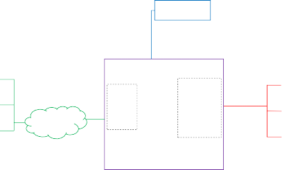
A Bridge serves to allow the use of non-Matter IoT devices (e.g. devices on a Zigbee or Z-Wave network, or any other non-Matter connectivity technology) in a Matter Fabric, with the goal to enable the consumer to keep using these non-Matter devices together with their Matter devices.
This is illustrated in the figure below: the non-Matter devices are exposed as Bridged Devices to Nodes on the Fabric. The Matter Nodes can communicate with both the (native) Matter devices as well as the Bridged Devices (by virtue of the Bridge which performs the translation between Matter and the other protocol).
Acts as an
interpreter
Assumes
Presents
for Bridged
responsibility
a Matter
Devices
for securing
interface
and
and certifying
to the
presents
the communi-
Matter
them as
cation link to
apps
Matter
each Bridged
Devices to
Device
the various
Matter apps
Matter Fabric
Matter App 3
Matter App 2
Matter App 1
Bridged
Device 3
Bridged
Device 2
Bridged
Device 1
Bridge
Manufacturer App
Non-Matter Transport Layer ( e.g. Zigbee; Z-Wave; proprietary; etc.)
See and control all of the Bridged Devices and Matter Devices using Matter protocol
Manufacturer -
defined interface
Matter Device 1
Matter Device 2
Matter Device 3
Matter Device 4
Figure 40. principle of bridging

NOTE
The bridging-concept described here is NOT intended to be used to expose Matter Nodes (which are not on the Fabric) to a Fabric, since direct connection of those Matter Nodes to the Fabric would provide a better experience.
This section will describe how the Data Model concepts can be used by a Bridge to expose the Bridged Devices in such a way that they can be discovered and used by Nodes on the Matter Fabric.
Exposing functionality and metadata of Bridged Devices
After Commissioning, the Bridge SHALL expose (at least) one Node to the Fabric. The device implementing the Bridge MAY have more than one Node. This, however, is orthogonal to the bridging concept and will not be discussed further here.
On this Node, the Bridge SHALL expose a set of endpoints representing the various Bridged Devices on the non-Matter side of the Bridge.
Additionally, it SHALL expose an endpoint with the device type Aggregator which has a Descriptor cluster with a PartsList attribute containing all the endpoints representing those Bridged Devices. See Endpoint Composition for the concept of hierarchical composition.
Each Bridged Device corresponds to an endpoint listed in this PartsList (see examples below). The Descriptor cluster on the corresponding endpoint provides information about the particular Bridged Device, such as its device type(s).

Descriptor cluster: DeviceTypeList: Root Node PartsList: EP 1, 11,12,13,14,15,16
Basic Information cluster:
..
EP 0
Descriptor cluster: DeviceTypeList: Aggregator PartsList: EP 11,12,13,14,15,16
EP 1
The PartsList on endpoint 1 lists all endpoints for bridged devices; each endpoint 11..16 represents one device at the non-Matter side of the bridge.

Descriptor cluster:
EP 11
Descriptor cluster:
EP 14
DeviceTypeList: Extended Color Light, Bridged Node
Bridge Device Basic Information cluster:
NodeLabel: "dining table"
DeviceTypeList: Generic Switch, Bridged Node
Bridge Device Basic Information cluster:
NodeLabel: "living room entrance"

Descriptor cluster:
EP 12
Descriptor cluster:
EP 15
DeviceTypeList: Extended Color Light, Bridged Node
Bridge Device Basic Information cluster:

Descriptor cluster:
DeviceTypeList: Dimmable Light, Bridged Node
Bridge Device Basic Information cluster:
NodeLabel: "hallway"
EP 13
Descriptor cluster:
DeviceTypeList: Generic Switch, Bridged Node
Bridge Device Basic Information cluster:
NodeLabel: "kitchen entrance"
EP 16
NodeLabel: "kitchen"
DeviceTypeList: Temperature Sensor, Bridged Node
Bridge Device Basic Information cluster:
NodeLabel: "outdoor temperature"
Figure 41. example of endpoints representing Bridged Devices
In case the Bridge is bridging to/from multiple technologies (or has some other logical distinction between groups of bridged devices), it MAY expose such groups as two or more such hierarchical trees each with their Aggregator device type (e.g. one for each technology, see figure below); it MAY also combine all bridged devices in one hierarchical tree (see figure above). Both figures have the same set of bridged devices - the difference is in how the bridge manufacturer decides to expose them as one or multiple sets.
Descriptor cluster:
DeviceTypeList: Root Node PartsList: EP 1,2, 11,12,13,14,15,16
Basic Information cluster:
..
EP 0
This implementation chooses to expose two instances of the Aggregator device type, each with their own hierarchy of devices, to be able to expose which bridged device is on which technology.
Descriptor cluster: DeviceTypeList: Aggregator PartsList: EP 11,12,13
Fixed Label cluster:
LabelList: [[" bridge","Zigbee"]]
Descriptor cluster:
EP 1

Descriptor cluster: DeviceTypeList: Aggregator PartsList: EP 14,15,16
Fixed Label cluster:
LabelList: [[" bridge","Z-Wave"]]
EP 2

Descriptor cluster:
DeviceTypeList: Generic Switch, Bridged Node
Bridge Device Basic Information cluster:
NodeLabel: "living room entrance"
EP 14
Descriptor cluster: EP 15
DeviceTypeList: Temperature Sensor, Bridged Node
Bridge Device Basic Information cluster:
NodeLabel: "outdoor temperature"
Descriptor cluster:
DeviceTypeList: Generic Switch, Bridged Node
Bridge Device Basic Information cluster:
NodeLabel: "kitchen entrance"
Z-Wave devices
EP 16
EP 11
DeviceTypeList: Extended Color Light, Bridged Node
Bridge Device Basic Information cluster:
NodeLabel: "dining table"
Descriptor cluster:
EP 12
DeviceTypeList: Extended Color Light, Bridged Node
Bridge Device Basic Information cluster:
NodeLabel: "kitchen"
Descriptor cluster:
DeviceTypeList: Dimmable Light, Bridged Node
Bridge Device Basic Information cluster:
NodeLabel: "hallway"
EP 13
Zigbee devices
Figure 42. example of endpoints representing Bridged Devices from two technologies
Topology or logical grouping
A Bridge typically has information on topology or logical grouping of the Bridged Devices, which can be of use to Nodes on the Matter Fabric.
For example, consider a Bridge with 50 lights. If this exposure of grouping, and their naming, would not be present, the user would just see a flat list of 50 lights on their controller and would not know which of those physical lights would be in which location/group.
If a Bridge has such information on topology or logical grouping, it SHOULD expose such information in the EndpointLists attribute of an Actions cluster (the ActionLists of which MAY be
empty if no actions are exposed). A Bridge MAY make it possible (e.g., through a Bridge Manufacturer’s app) for its users to restrict whether all or some of such information is exposed to the Fabric. The Node on the Fabric using the Bridged Devices which is interested in using such topology or logical grouping (e.g. to show the grouping of lights per room in an overview to the user), SHOULD derive such grouping (and associated naming) from this EndpointLists attribute.
In the example below, the devices are split over two rooms, as exposed in the EndpointLists attribute. This example also illustrates a composed endpoint for a composed Bridged Device, in this case a lighting device (Bridged Device at EP 24,25,26) which has an up- and downlighter which can be controlled separately, and which have their own set of lighting-related clusters on an individual endpoint (EP 25,26). Note that the Bridged Device Basic Information cluster is at the top of the hierarchy for this composed device (EP 24), while the application device types and application clusters are at the leaf endpoints (EP 25,26).
Since EP 25,26 are listed in the PartsList of EP 24, they 'inherit' the Bridged Node device type and information in the Bridged Device Basic Information cluster of EP 24.
Descriptor cluster:
DeviceTypeList: Root Node
EP 0
Descriptor cluster:
DeviceTypeList: Aggregator PartsList: EP 12,13,14,22,23,24,25,26
Actions cluster:
ActionList: [ ] EndpointLists: [
[0xE001, "living room", room, [12,13,14] ],
[0xE002, "bedroom", room, [22,23,24,25,26] ]
]
EP 1
PartsList: EP 1, 12,13,14,22,23,24,25,26
Basic Information cluster:
..
In this example, the Actions cluster is used to indicate grouping, i.e. which devices are in which room. The bedroom has 3 bridged devices, and one of them (endpoint 24,25,26) is a composed device - it uses the Fixed Label cluster to expose information on the user-relevant components of the composed device (endpoint 25,26).
composed device
Descriptor cluster:
EP 22
Descriptor cluster:
EP 12
DeviceTypeList: Extended Color Light, Bridged Node
Bridge Device Basic Information cluster:
NodeLabel: "dining table"
DeviceTypeList: Color Temperature Light, Bridged Node
Bridge Device Basic Information cluster:
NodeLabel: "ceiling light"
Descriptor cluster: DeviceTypeList: Bridged Node PartsList: 25,26
Bridge Device Basic Information cluster:
NodeLabel: "bedroom light"
EP 24
Descriptor cluster: EP 23
Descriptor cluster:
EP 13
DeviceTypeList: Color Temperature Light, Bridged Node
Bridge Device Basic Information cluster:
NodeLabel: "kitchen light"
EP 14
DeviceTypeList: Temperature Sensor, Bridged Node, Power Source
Bridge Device Basic Information cluster:
NodeLabel: "bedroom temperature"
Power Source Configuration cluster:
Sources: EP 23
Power Source cluster: (features=BAT,REPLC) BatChargeLevel : Warning BatReplacementDescription : "AAA batteries"
BatQuantity: 2
bedroom
Descriptor cluster: EP 25
DeviceTypeList: Extended Color Light
Fixed Label cluster:
LabelList: [["orientation","up "]]
Descriptor cluster:
DeviceTypeList: Generic Switch, Bridged Node
Bridge Device Basic Information cluster:
NodeLabel: "living room entrance"
living room
Descriptor cluster:
DeviceTypeList: Extended Color Light
Fixed Label cluster:
LabelList: [["orientation","down "]]
EP 26
Figure 43. example of endpoints representing Bridged Devices using grouping

living room
dining table
kitchen light
living room entrance
bedroom
ceiling light
bedroom light
bedroom light up
bedroom light down
bedroom temperature
Figure 44. impression of app UI indicating information for the Bridged Devices
Native Matter functionality in Bridge
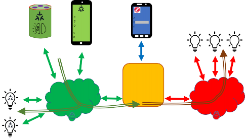
The Bridge MAY also contain native Matter functionality, i.e. non-bridged functionality, such as in the example below, which shows a smart speaker device having, in addition to a Wi-Fi connection, also a Zigbee connection towards a number of Zigbee lights. The speaker functionality (EP 31) is native Matter functionality (and could have a Controller role to allow sending Matter commands upon receiving voice commands), while the remainder of the non-zero endpoints represent the Bridged Devices.
Descriptor cluster: DeviceTypeList: Aggregator PartsList: EP 12,13,14,22,24
Actions cluster:
ActionList: [ ] EndpointLists: [
[0xE001, "living room", room, [12,13,14] ],
[0xE002, "bedroom", room, [22,24,31] ]
EP 1
Descriptor cluster: DeviceTypeList: Root Node PartsList: EP 1, 12,13,14,22,24,31

Basic Information cluster:
..
EP 0
In this example, the EndPointLists attribute of the Actions cluster is used to indicate grouping (e.g. all devices in one room - irrespective whether they are bridged or not).
EP31 is a component of the device itself which is not bridged,
i.e. native Matter; it is in the bedroom along with some bridged devices.
]
Descriptor cluster:
EP 12
EP 31
DeviceTypeList: Extended Color Light, Bridged Node
Bridge Device Basic Information cluster:
NodeLabel: "dining table"
Descriptor cluster:
DeviceTypeList: Speaker
Descriptor cluster:
EP 13
Descriptor cluster:
EP 22
DeviceTypeList: Color Temperature Light, Bridged Node
Bridge Device Basic Information cluster:
NodeLabel: "kitchen light"
DeviceTypeList: Color Temperature Light, Bridged Node
Bridge Device Basic Information cluster:
NodeLabel: "ceiling light"
Descriptor cluster:
DeviceTypeList: Generic Switch, Bridged Node
Bridge Device Basic Information cluster:
NodeLabel: "living room entrance"
living room
EP 14
Descriptor cluster:
DeviceTypeList: Generic Switch, Bridged Node
Bridge Device Basic Information cluster:
NodeLabel: "bedside switch"
bedroom
EP 24
Figure 45. example of Bridge with native Matter functionality
Information about Bridged Devices
For each Bridged Device, the Bridge SHALL include a Bridged Device Basic Information cluster on the endpoint which represents this Bridged Device.
Furthermore, the Bridge SHALL include a Descriptor cluster with
a DeviceTypeList attribute containing device type Bridged Node plus the device type(s) of the Bridged Device, and
a PartsList attribute listing any other endpoints which jointly expose the functionality of this Bridged Device.
In case a Bridged Device is represented by multiple endpoints, the Bridged Device Basic Information and Descriptor clusters SHALL only be present on the endpoint which is the top level of the hierarchy representing this Bridged Device (example: endpoint 24 in Figure 43, “example of endpoints representing Bridged Devices using grouping”).
In case the Bridged Device contains a power source such as battery or mains power feed, and information about the state of that power source is available to the Bridge, the Bridge SHALL also include a Power Source Configuration cluster and a Power Source cluster on the endpoint representing the Bridged Device. An example of this is shown for the battery-powered temperature sensor on endpoint 23 in Figure 43, “example of endpoints representing Bridged Devices using grouping”.
Two special cases:
In case such Bridged Device is represented by multiple endpoints, and the Bridged Device contains only one power source, the Power Source Configuration cluster SHALL be present on the endpoint which is the top level of the hierarchy representing this Bridged Device, while the Power Source cluster SHALL be present on the endpoint which corresponds to the part of the Bridged Device containing the power source.
In case a Bridged Device contains multiple power sources, each of these power sources SHALL be represented by a Power Source cluster on the endpoint which corresponds to the part of the Bridged Device containing the power source (no more than one such cluster per endpoint). The Power Source Configuration cluster SHALL be present on the endpoint which is the top level of the hierarchy representing this Bridged Device, referencing the endpoints where the Power Source clusters for this Bridged Device are present.
In case a Bridged Device does not contain a power source such as battery or mains power feed, or information about the state of that power source is not available to the Bridge, the Bridge SHALL NOT include a Power Source Configuration cluster and a Power Source cluster on the endpoint representing the Bridged Device.
Clusters for Bridged Device functionality (device types)
For each Bridged Device, the Bridge SHALL expose the clusters required for a device of the indicated Matter device type(s).
This allows the Matter Nodes to recognize the device type of the Bridged Device and interact with its clusters in the same manner as with a native Matter Node of that device type.
Discovery of Bridged Devices
A Node which discovers another Node with device type Aggregator on one of its endpoints SHOULD walk the entire tree of endpoints via the PartsList attributes and endpoints to discover the list of Bridged Devices, including their device types and other attributes, as well as any native Matter functionality potentially present on the Node.
Each endpoint found containing a Bridged Node device type represents a Bridged Device of the device type(s) specified at this endpoint, or one of the endpoints found via its PartsList. If the discovering Node supports this device type, it MAY add this Bridged Device to the list of devices which it could interact with, or could set up configuration for.
This discovering Node SHALL use the acquired information on the available Bridged Devices to set up (configure) (likely with input from the user) how the Bridged Devices can be used with the Matter Nodes (e.g. which switch controls which light, or how to control a light from an app on the user’s phone).
Since the Bridge may expose a large number of Bridged Devices, the discovering Node SHALL use the NodeLabel attribute in the Bridged Device Basic Information cluster of each of the Bridged Devices to allow the user to easily identify and recognize the various Bridged Devices, and expedite the setup/configuration process, rather than present the user with an unannotated list of, for example, 20 lights, 3 sensors and 4 switches. These labels have likely been populated by the user when interacting previously with the Bridge e.g. through means provided by the Bridge Manufacturer, such as a Bridge Manufacturer app.
If power source-related information regarding the Bridged Device is provided in the Power Source
cluster on the associated endpoint, the discovering Node SHOULD use this information in a similar
manner as power source-related information acquired from a Matter Node’s Power Source cluster. Such information can then be used to inform the user about the state of the power source (e.g. warn about low batteries) in a Bridged Device in a similar manner as done for Matter Nodes.
Configuration of Bridged Devices
For configuration of the discovered Bridged Devices, two basic archetypes are described in the following sections: one for actuators and one for sensors/switches.
Since a Bridged Device of a certain device type has the same set of application clusters as a native Matter device of the same device type, this process is similar to configuring a native Matter device of that device type.
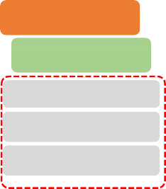
Sending commands from a Matter controller to a Bridged Device
For Bridged Devices that are actuators and hence have a Controlee role, a Controller Node on the Fabric MAY send commands to the associated clusters on one or more endpoints on the Bridge’s Node, such as an On command to the On/Off cluster of a Bridged Device. The Bridge SHALL forward this command to the relevant Bridged Device after conversion between the Matter protocol and the non-Matter device’s native protocol.
Example:
A Controller creates a Group containing some Matter lights as well as some non-Matter lights, by sending an Add Group command to the instances of the Group cluster on both the endpoints of the Matter lights as well as on the Bridge’s Node endpoints representing the targeted bridged lights.
Similarly, the Controller creates one or more Scenes using the instances of the Scene cluster on these endpoints.
The Controller then sends a (single) On command (On/Off cluster) to this group to switch on all these lights in a single operation. This (single) multicast message will be received (and interpreted) by the Matter lights which are part of this group as well as by the Bridge, which will forward it (after appropriate protocol conversion) to the relevant bridged lights.
Similarly, the Controller sends a (single) Move to Level (Level Control cluster) or sends a (single) Recall Scene (Scene cluster) to this group, to set the brightness resp. recall a scene contents on all these lights in a single operation.
Matter controllers & apps Bridge Manufacturer app

Cooking island
Living room
Uplighter
Downlighter
Reading light
Kitchen
Ceiling
Living room
Uplighter Downlighter
lights
Reading light
Matter lights
Matter network
bridge Matter
<=>
Zigbee
bridged lights
Zigbee network
Matter light control Zigbee light control
Figure 46. example of bridging lights
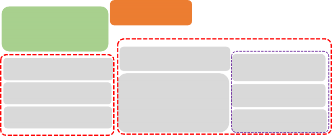
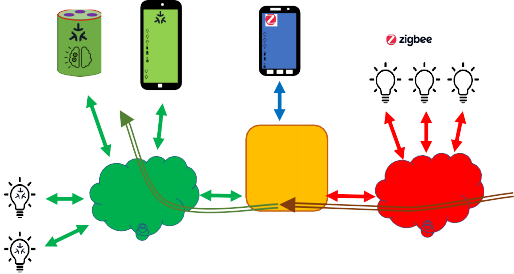
Receiving status/events/commands from a Bridged Device
For Bridged Devices like sensors and switches, the Bridge will receive value updates (e.g. Zigbee attribute reports), events and/or commands from those devices, and SHALL (after conversion from the native protocol of the non-Matter devices towards Matter protocol) represent those as attributes, events and/or commands in the appropriate clusters on the associated endpoints of the Bridge.
Interactions with those attributes/events/commands on the Matter side (e.g., towards a Controller using the sensor/switch data) SHOULD be identical to interactions with corresponding attributes/events/commands in native Matter sensors and switches (e.g., attribute readout and subscription, proxying and eventing).
Examples:
A temperature sensor sends a status report to the Bridge over a non-Matter interface. The logic in the Bridge processes this as an update to the Measured Value attribute of the Temperature Measurement cluster on the endpoint associated with this bridged sensor.
Nodes on the Fabric which have an interest in this value can read the updated attribute value, and can configure a subscription on this attribute. This is identical to reading an attribute value or setting up an attribute subscription on a native-Matter temperature sensor Node.
A user presses a button on a (push-button) switch device. The switch device sends a message to the Bridge over a non-Matter interface. The logic in the Bridge processes this to generate an InitialPress event (Switch cluster) on the endpoint representing the switch.
Nodes on the Fabric which have an interest in the switch operation can setup eventing from this cluster.
Matter controllers & apps Bridge Manufacturer app
Living room
Uplighter
Downlighter
Reading light
Switch 1 ON
Switch 2 OFF
Temp: 20 °C
Kitchen
Ceiling
Cooking island
Living room
Uplighter
Downlighter
Reading light
Switch 1 ON
Switch 2 OFF
Temp: 20 °C
lights
Matter lights
Matter network
bridge Matter
<=>
Zigbee Zigbee
network
bridged switches/sensors

sensors & switches


Matter switch/sensor state Zigbee switch/sensor state
Figure 47. example of bridging switches and sensors
New features for Bridged Devices
Bridged Devices can have their software updated independently of the Bridge, through Bridge Manufacturer-specific means. These updates MAY result in one or more changes to their capabilities, such as supported clusters and/or attributes, for an endpoint. Like every Matter Node, every endpoint on the Bridge’s Node contains a Descriptor cluster that contains attributes for the device types, endpoints (PartsList) and supported clusters. Nodes that wish to be notified of such changes SHOULD monitor changes of these attributes.
Changes to the set of Bridged Devices
Bridged Devices can be added to or removed from the Bridge through Bridge-specific means. For example, the user can use a Manufacturer-provided app to add/remove Zigbee devices to/from their Matter-Zigbee Bridge.
When an update to the set of Bridged Devices (which are exposed according to the Section 9.12.11, “Best practices for Bridge Manufacturers”) occurs, the Bridge SHALL
on the Descriptor clusters of the root node endpoint and of the endpoint which holds the
Aggregator device type: update the PartsList attribute (add/remove entries from this list)
update the exposed endpoints and their descriptors according to the new set of Bridged Devices
Nodes that wish to be notified of added/removed devices SHOULD monitor changes of the PartsList attribute in the Descriptor cluster on the root node endpoint and the endpoint which holds the Aggregator device type.
Allocation of endpoints for Bridged Devices SHALL be performed as described in Dynamic Endpoint allocation.
Changes to device names and grouping of Bridged Devices
Typically, the user has some means (e.g. a Manufacturer-provided app) to assign names to the Bridged Devices, or names could be assigned automatically by the Bridge. The Bridge SHALL expose such names in the NodeLabel attribute of the Bridged Device Basic Information cluster on the applicable endpoint.
Similarly, the user typically has some means to group the Bridged Devices (e.g. via a room/zone- concept) and provide names to such groups, or grouping could be applied automatically by the Bridge. The Bridge SHOULD expose such grouping using the EndpointLists attribute of the Actions cluster as described above.
For such exposed information, when there is a change in naming/grouping (e.g. the user makes changes via a Manufacturer-provided app), the Bridge SHALL update the appropriate attributes.
Nodes that wish to be notified of a change in such a name or grouping SHOULD monitor changes of this attribute or cluster.
Setup flow for a Bridge (plus Bridged Devices)
As described above, the Bridge together with its Bridged Devices is exposed as a single Node with a list of endpoints. Consequently, a single Node ID and a single Operational Certificate is assigned during Commissioning and a single pass through the commissioning flow is required to bring the Bridge (along with its Bridged Devices) onto a Fabric. This provides for a simple user experience, since the user only needs to go through the commissioning flow for the Bridge, and not separately for each of the Bridged Devices.
Access Control
The Bridge is a Matter node, therefore it has a single Access Control Cluster for the entire Node, like every other Matter Node. This cluster contains all Access Control Entries for each of its endpoints, including for all Bridged Devices and other native Matter functionality exposed by the Bridge Node. A typical setup of Access Control would reflect which privilege level a Matter Controller needs to have for one or more Bridged Devices. This overall access set may be a subset of all the Bridged Devices on the Bridge, rather than all endpoints on a Bridge. This can be accomplished by setting an Access Control Entry containing as targets a list of those endpoints representing a Bridged Device or a set of Bridged Devices. As defined in the ACL model, it is also possible to specify access towards specific Targets, for example all Bridged Devices of device type Extended Color Light.
Software update (OTA)
The Bridge is a Matter device and its Matter-related functionality MAY be updated using the mechanism described in Section 11.20, “Over-the-Air (OTA) Software Update”.
The Bridged Devices, on the other hand, are not native Matter devices, do not have a Product ID, and are not listed in the Distributed Compliance Ledger. They are typically updated using a mechanism defined and deployed by the Bridge Manufacturer. That same mechanism is typically used to update the parts of the Bridge which are not related to Matter, which is particularly relevant to allow synchronization of updates to the non-Matter part of the Bridge with updates to the Bridged Devices. Obviously, such mechanism MAY also be employed to update the entire Bridge firmware, including the Matter-related functionality.
Best practices for Bridge Manufacturers
This section summarizes (in order of priority) the process to determine which non-Matter devices the Bridge exposes to the Fabric.
Choice of supported device types
A Manufacturer MAY choose which of the Matter device types they can or want to support in the Bridge. After implementation of support for bridging of those device types, they SHALL certify the Bridge for those device types.
By default, a Bridge SHOULD expose to the Fabric all its connected non-Matter devices which can be mapped to a Matter device type for which that Bridge is certified.
E.g., if a Bridge is certified for Matter light bulbs, it SHOULD NOT hide any light bulb on the non-Matter side from the Fabric by default (some situations where the Bridge MAY deviate from this recommendation are in the following text).
Given the wide variety of device types on a wide variety of standards, there may be device types on the non-Matter side that do not have a corresponding Matter device type. Such devices cannot be bridged to a Matter device type. The Manufacturer MAY choose to not expose such devices with the Bridge or MAY expose them with a manufacturer-specific device type and/or manufacturer-specific clusters.
Compatibility issues
For the device types for which a Bridge is certified, a Bridge Manufacturer MAY decide to not expose certain devices based on any reason, including compatibility and interoperability reasons, or to expose them in a 'best-effort' manner as needed.
The Bridge Manufacturer may choose to not expose a device that does not support certain functions or features which are mandatory for a Matter device type, but which are defined as optional, or not defined at all, in the specification for the corresponding device type on the non-Matter side of the bridge. Such a Bridge would expose to the Fabric only Bridged Devices of device types which support those particular control functions or features which are required.
The Bridge Manufacturer may also choose to map or emulate such features which are not available in the Bridged Device; example: for a bridged colored light connected via a protocol which does not support scenes, the Bridge could emulate the scene function by storing the scenes in the Bridge and sending corresponding brightness and color commands to the light when a Scene Recall command is received from a Matter Node.
User choice
A Bridge MAY make it possible (e.g., through a Bridge Manufacturer’s app) for its users to further restrict which devices are exposed to the Fabric.
For example, a user may decide to prevent exposure to the Fabric of certain Devices Types, such as all occupancy sensors, or of only certain devices of a certain device type, such as only their bedroom occupancy sensor.
Best practices for Administrators
An Administrator MAY indicate to users which devices are native Matter and which ones are Bridged Devices, as determined using the presence of a Bridged Node device type on the endpoint, in
order to ensure the user does not make assumptions about the Bridged Devices having the same security requirements as native Matter devices.
Bridged Device Basic Information Cluster
Scope & Purpose
This Cluster serves two purposes towards a Node communicating with a Bridge:
indicate that the functionality on the Endpoint where it is placed (and its Parts) is bridged from a non-Matter technology, and
provide a centralized collection of attributes that the Node MAY collect to aid in conveying information regarding the Bridged Device to a user, such as the vendor name, the model name, or user-assigned name.
This cluster SHALL be exposed by a Bridge on the Endpoint representing each Bridged Device. When the functionality of a Bridged Device is represented using a set of Endpoints, this cluster SHALL only be exposed on the Endpoint which is at the top of the hierarchy for the functionality of that Bridged Device.
This cluster SHALL NOT be used on an endpoint that is not in the Descriptor cluster PartsList of an endpoint with an Aggregator device type.
This cluster has been derived from the Basic Information Cluster, and provides generic information about the Bridged Device. Not all of the attributes in the Basic Information Cluster are relevant for a Bridged Device (e.g. ProductID since it is not a Matter Device). For other attributes, the information which is listed as Mandatory for the Basic Information Cluster, may not be available when the Bridged Device does not provide it to the Bridge, and the Bridge has no other means to determine it. For such cases where the information for a particular attribute is not available, the Bridge SHOULD NOT include the attribute in the cluster for this Bridged Device. See below for Conformance details.
Revision History
The global ClusterRevision attribute value SHALL be the highest revision number in the table below.
Revision
Description
1
Initial Release
Classification
Hierarchy
Role
Context
PICS Code
Derived from Basic Information
Utility
Endpoint
BRBINFO
Cluster Identifiers
Identifier
Name
0x0039
Bridged Device Basic Information
Features
This Cluster has no Features.
Attributes
Name
Conformance
DataModelRevision
X
VendorName
O
VendorID
O
ProductName
O
ProductID
X
NodeLabel
O
Location
X
HardwareVersion
O
HardwareVersionString
O
SoftwareVersion
O
SoftwareVersionString
O
ManufacturingDate
O
PartNumber
O
ProductURL
O
ProductLabel
O
SerialNumber
O
LocalConfigDisabled
X
Reachable
M
UniqueID
O
CapabilityMinima
X
Since this cluster has been derived from the Basic Information Cluster, the identifiers of the attributes, their range, quality and default characteristics and their descriptions correspond to those in that Cluster and those descriptions are not repeated here. Several attributes from the Basic Information Cluster which are not relevant or applicable for a Bridged Device have been marked with X in column Conformance and SHALL NOT be used in the Bridged Device Basic Information Cluster.
The Conformance characteristics of several attributes in this cluster have changed from M to O
compared to their Conformance in the Basic Information Cluster, and SHALL be used according to the table above.
The Bridge SHOULD fill these attributes with the available information, which could e.g. come from the Bridged Device provided to the Bridge over the non-Matter interface (e.g. VendorName and VendorID) or could have been provided by the user (e.g. assigned name of a device for NodeLabel).
If the manufacturer of a Bridged Device is known to the Bridge, the Bridge SHALL provide this name (in attribute VendorName), otherwise it SHALL NOT include this attribute.
If the manufacturer of a Bridged Device and the associated Alliance-assigned Vendor ID are known to the Bridge (e.g. by copying the Manufacturer Code from the Node Descriptor of a Zigbee device), the Bridge SHALL provide this identifier (in attribute VendorID), otherwise it SHALL NOT include this attribute.
The Reachable attribute SHALL be used to indicate whether the bridged device is reachable by the bridge over the non-Matter network, so a Matter Node which wants to communicate with a bridged device can get an indication that this might fail (when the attribute is False). Determination of reachability MAY not be perfect (e.g. depending on technology employed), so the Matter Node SHOULD be aware of the risk of false positives and negatives on reachability determination. For example, a bridged device MAY be marked as unreachable while it could actually be reached, and vice-versa.
Also see event ReachableChanged below.
The UniqueID attribute (when present) for a Bridged Device SHOULD be updated when the Bridge is factory reset.
Events
This cluster SHALL support these events:
Name
Conformance
StartUp
O
ShutDown
O
Leave
O
ReachableChanged
M
9.13.7.1. ReachableChanged Event
This event SHALL be generated when there is a change in the Reachable attribute. Its purpose is to provide an indication towards interested parties that the reachability of a bridged device (over the non-Matter network) has changed, so they MAY take appropriate action.
After (re)start of a bridge this event MAY be generated.
Actions Cluster
Scope & Purpose
This cluster provides a standardized way for a Node (typically a Bridge, but could be any Node) to
expose
information about logical grouping of endpoints on the Node (example: lights in a room)
information about named actions that can be performed on such a group of endpoints (example: recall a scene for a group of lights by its name)
commands to trigger such actions
events to receive feedback on the state of such actions.
The information on grouping and available actions is typically provided by the user or Bridge manufacturer via some means not defined in Matter, and therefore provided as read-only to Nodes. For example: a manufacturer-provided app allows a user to set up logical grouping and create/assign scene for such groups.
Using this cluster, a Node can learn about such logical grouping, provided actions, and trigger such actions.
While the origin of this cluster stems from use cases with a Bridge, its server side may also be implemented on any Node which can expose certain grouping, actions or automations to other users.
After defining the attributes, commands and events for this cluster, and the associated data types, several examples are provided to illustrate the capabilities of this cluster.
Actions can be defined in a flexible manner to suit the needs of the various nodes implementing this cluster. For each action, the commands available for that particular action are defined.
This cluster can be used to expose only the grouping of endpoints without any actions defined by populating the EndpointList attribute accordingly and providing an empty list for ActionList.
The term 'action' in the description of this cluster should not be confused with the term 'action' as used in the Interaction Model.
Revision History
The global ClusterRevision attribute value SHALL be the highest revision number in the table below.
Revision
Description
1
Initial Release
Classification
Hierarchy
Role
Context
PICS Code
Base
Application
Node
ACT
Cluster Identifiers
Identifier
Name
0x0025
Actions
Features
This cluster has no features defined.
Attributes
ID
Name
Type
Constraint
Quality
Default
Access
Conforma nce
0x0000
ActionList
list[ActionS truct]
max 256
empty
R V
M
0x0001
EndpointLi sts
list[Endpoi ntListStruc t]
max 256
empty
R V
M
0x0002
SetupURL
string
max 512
empty
R V
O
ActionList attribute
The ActionList attribute holds the list of actions. Each entry SHALL have an unique ActionID, and its EndpointListID SHALL exist in the EndpointLists attribute.
EndpointLists attribute
The EndpointLists attribute holds the list of endpoint lists. Each entry SHALL have an unique EndpointListID.
SetupURL attribute
The SetupURL attribute (when provided) SHALL indicate a URL; its syntax SHALL follow the syntax as specified in RFC 3986, max. 512 ASCII characters. The location referenced by this URL SHALL provide additional information for the actions provided:
When used without suffix, it SHALL provide information about the various actions which the cluster provides.
Example: SetupURL could take the value of example://Actions or https://www.example.com/ Matter/bridgev1/Actions for this generic case (access generic info how to use actions provided by this cluster).
When used with a suffix of "/?a=" and the decimal value of ActionID for one of the actions, it SHALL provide information about that particular action. This could be a deeplink to manufacturer-app/website (associated somehow to the server node) with the information/edit- screen for this action so that the user can view and update details of the action, e.g. edit the scene, or change the wake-up experience time period.
Commands
ID
Name
Direction
Response
Access
Conformance
0x00
InstantAction
client ⇒ server
Y
O
desc
0x01
InstantAction WithTransition
client ⇒ server
Y
O
desc
0x02
StartAction
client ⇒ server
Y
O
desc
0x03
StartActionWit hDuration
client ⇒ server
Y
O
desc
0x04
StopAction
client ⇒ server
Y
O
desc
0x05
PauseAction
client ⇒ server
Y
O
desc
0x06
PauseActionWi thDuration
client ⇒ server
Y
O
desc
0x07
ResumeAction
client ⇒ server
Y
O
desc
0x08
EnableAction
client ⇒ server
Y
O
desc
0x09
EnableActionW ithDuration
client ⇒ server
Y
O
desc
0x0a
DisableAction
client ⇒ server
Y
O
desc
0x0b
DisableAction WithDuration
client ⇒ server
Y
O
desc
Conformance: a server SHALL support a command when it is listed in the SupportedCommands data field of one or more actions listed in the ActionList provided by the server.
Some general requirements and data fields for all the commands:
The ActionID data field SHALL indicate the action identifier. If there is no entry the in ActionList holding the same action identifier, a response shall be generated with the StatusCode NOT_FOUND.
The InvokeID data field MAY be provided by the client when invoking a command. When this value is provided, the server SHALL generate a StateChanged event when the action changes to a new state or an ActionFailed event when execution of the action fails; in the data of such events, the value of the InvokeID data field from the invoke will be provided, so that the client can relate the event back to the corresponding command. It is up to the client to determine which value is provided in InvokeID. When sending multiple commands for the same action, with different InvokeID, the server SHALL provide in the event the InvokeID value from the most recent command for a particular ActionID.
If the command refers to an action which currently is not in a state where the command applies, a response shall be generated with the StatusCode INVALID_COMMAND.
Actions are typically mapped to state changes of the involved endpoints. Those endpoints can also be controlled with commands from other clusters, controlled by other nodes and impacted by non-Matter interactions (e.g. local controls). Such other interactions can cause the state of the endpoints to differ from the results of the command which triggered the action. A client interested in such changes can use the InvokeID data field (see above) to receive events StateChanged and ActionFailed for feedback for such cases.
InstantAction Command
This command SHALL have the following data fields:
ID
Name
Type
Constraint
Quality
Default
Conformanc e
0
ActionID
uint16
all
M
1
InvokeID
uint32
all
O
This command triggers an action (state change) on the involved endpoints, in a "fire and forget" manner. Afterwards, the action’s state SHALL be Inactive.
Example: recall a scene on a number of lights.
InstantActionWithTransition Command
This command SHALL have the following data fields:
ID
Name
Type
Constraint
Quality
Default
Conformanc e
0
ActionID
uint16
all
M
1
InvokeID
uint32
all
O
2
TransitionTi me
uint16
all
MS
M
The TransitionTime data field SHALL indicate the transition time in 1/10th of seconds. It is recommended that, where possible (e.g., it is not possible for attributes with Boolean data type), a gradual transition SHOULD take place from the old to the new state over this time period. However, the exact transition is manufacturer dependent.
This command triggers an action (state change) on the involved endpoints, with a specified time to transition from the current state to the new state. During the transition, the action’s state SHALL be Active. Afterwards, the action’s state SHALL be Inactive.
Example: recall a scene on a number of lights, with a specified transition time.
StartAction Command
This command SHALL have the following data fields:
ID
Name
Type
Constraint
Quality
Default
Conformanc e
0
ActionID
uint16
all
M
1
InvokeID
uint32
all
O
This command triggers the commencement of an action on the involved endpoints. Afterwards, the action’s state SHALL be Active.
Example: start a dynamic lighting pattern (such as gradually rotating the colors around the setpoints of the scene) on a set of lights.
Example: start a sequence of events such as a wake-up experience involving lights moving through several brightness/color combinations and the window covering gradually opening.
StartActionWithDuration Command
This command SHALL have the following data fields:
ID
Name
Type
Constraint
Quality
Default
Conformanc e
0
ActionID
uint16
all
M
1
InvokeID
uint32
all
O
2
Duration
uint32
all
MS
M
The Duration data field SHALL indicate the requested duration in seconds.
This command triggers the commencement of an action on the involved endpoints, and SHALL change the action’s state to Active. After the specified Duration, the action will stop, and the action’s state SHALL change to Inactive.
Example: start a dynamic lighting pattern (such as gradually rotating the colors around the setpoints of the scene) on a set of lights for 1 hour (Duration=3600).
StopAction Command
This command SHALL have the following data fields:
ID
Name
Type
Constraint
Quality
Default
Conformanc e
0
ActionID
uint16
all
M
1
InvokeID
uint32
all
O
This command stops the ongoing action on the involved endpoints. Afterwards, the action’s state SHALL be Inactive.
Example: stop a dynamic lighting pattern which was previously started with StartAction.
PauseAction Command
This command SHALL have the following data fields:
ID
Name
Type
Constraint
Quality
Default
Conformanc e
0
ActionID
uint16
all
M
1
InvokeID
uint32
all
O
This command pauses an ongoing action, and SHALL change the action’s state to Paused.
Example: pause a dynamic lighting effect (the lights stay at their current color) which was previously started with StartAction.
PauseActionWithDuration Command
This command SHALL have the following data fields:
ID
Name
Type
Constraint
Quality
Default
Conformanc e
0
ActionID
uint16
all
M
1
InvokeID
uint32
all
O
2
Duration
uint32
all
MS
M
The Duration data field SHALL indicate the requested duration in seconds.
This command pauses an ongoing action, and SHALL change the action’s state to Paused. After the specified Duration, the ongoing action will be automatically resumed. which SHALL change the action’s state to Active.
Example: pause a dynamic lighting effect (the lights stay at their current color) for 10 minutes (Duration=600).
The difference between Pause/Resume and Disable/Enable is on the one hand semantic (the former is more of a transitionary nature while the latter is more permanent) and on the other hand these can be implemented slightly differently in the implementation of the action (e.g. a Pause would be automatically resumed after some hours or during a nightly reset, while an Disable would remain in effect until explicitly enabled again).
ResumeAction Command
This command SHALL have the following data fields:
ID
Name
Type
Constraint
Quality
Default
Conformanc e
0
ActionID
uint16
all
M
1
InvokeID
uint32
all
O
This command resumes a previously paused action, and SHALL change the action’s state to Active.
The difference between ResumeAction and StartAction is that ResumeAction will continue the action from the state where it was paused, while StartAction will start the action from the beginning.
Example: resume a dynamic lighting effect (the lights' colors will change gradually, continuing from the point they were paused).
EnableAction Command
This command SHALL have the following data fields:
ID
Name
Type
Constraint
Quality
Default
Conformanc e
0
ActionID
uint16
all
M
1
InvokeID
uint32
all
O
This command enables a certain action or automation. Afterwards, the action’s state SHALL be Active.
Example: enable a motion sensor to control the lights in an area.
EnableActionWithDuration Command
This command SHALL have the following data fields:
ID
Name
Type
Constraint
Quality
Default
Conformanc e
0
ActionID
uint16
all
M
1
InvokeID
uint32
all
O
2
Duration
uint32
all
MS
M
The Duration data field SHALL indicate the requested duration in seconds.
This command enables a certain action or automation, and SHALL change the action’s state to be Active. After the specified Duration, the action or automation will stop, and the action’s state SHALL change to Disabled.
Example: enable a "presence mimicking" behavior for the lights in your home during a vacation; the Duration field is used to indicated the length of your absence from home. After that period, the presence mimicking behavior will no longer control these lights.
DisableAction Command
This command SHALL have the following data fields:
ID
Name
Type
Constraint
Quality
Default
Conformanc e
0
ActionID
uint16
all
M
1
InvokeID
uint32
all
O
This command disables a certain action or automation, and SHALL change the action’s state to Inactive.
Example: disable a motion sensor to no longer control the lights in an area.
DisableActionWithDuration Command
This command SHALL have the following data fields:
ID
Name
Type
Constraint
Quality
Default
Conformanc e
0
ActionID
uint16
all
M
1
InvokeID
uint32
all
O
2
Duration
uint32
all
MS
M
The Duration data field SHALL indicate the requested duration in seconds.
This command disables a certain action or automation, and SHALL change the action’s state to Disabled. After the specified Duration, the action or automation will re-start, and the action’s state SHALL change to either Inactive or Active, depending on the actions (see examples 4 and 6).
Example: disable a "wakeup" experience for a period of 1 week when going on holiday (to prevent them from turning on in the morning while you’re not at home). After this period, the wakeup experience will control the lights as before.
Events
This cluster SHALL support these events:
Id
Name
Priority
Access
Conformance
0
StateChanged
INFO
V
M
1
ActionFailed
INFO
V
M
StateChanged Event
This event SHALL be generated when there is a change in the State of an ActionID during the execution of an action and the most recent command using that ActionID used an InvokeID data field.
It provides feedback to the client about the progress of the action. This event SHALL have the following data fields:
ID
Name
Type
Constraint
Quality
Default
Conformanc e
0
ActionID
uint16
M
1
InvokeID
uint32
M
2
NewState
ActionStateE num
M
The ActionID data field SHALL be set to the ActionID of the action which has changed state.
The InvokeID data field SHALL be set to the InvokeID which was provided to the most recent command referencing this ActionID.
The NewState data field SHALL be set to state that the action has changed to.
Example: When InstantActionWithTransition is invoked (with an InvokeID data field), two StateChanged events will be generated:
one when the transition starts (NewState=Active)
one when the transition completed (NewState=Inactive)
ActionFailed Event
This event SHALL be generated when there is some error which prevents the action from its normal planned execution and the most recent command using that ActionID used an InvokeID data field.
ID
Name
Type
Constraint
Quality
Default
Conformanc e
0
ActionID
uint16
M
1
InvokeID
uint32
M
2
NewState
ActionStateE num
M
3
Error
ActionError Enum
M
It provides feedback to the client about the non-successful progress of the action. This event SHALL have the following data fields:
The ActionID data field SHALL be set to the ActionID of the action which encountered an error.
The InvokeID data field SHALL be set to the InvokeID which was provided to the most recent command referencing this ActionID.
The NewState data field SHALL be set to state that the action is in at the time of generating the event.
The Error data field SHALL be set to indicate the reason for non-successful progress of the action.
Example: When InstantActionWithTransition is invoked (with an InvokeID data field), and another controller changes the state of one or more of the involved endpoints during the transition, thus interrupting the transition triggered by the action, two events would be generated:
StateChanged when the transition starts (NewState=Active)
ActionFailed when the interrupting command occurs (NewState=Inactive, Error=interrupted)
Example: When InstantActionWithTransition is invoked (with an InvokeID data field = 1), and the same client invokes an InstantAction with (the same or another ActionId and) InvokeID = 2, and this second command interrupts the transition triggered by the first command, these events would be generated:
StateChanged (InvokeID=1, NewState=Active) when the transition starts
ActionFailed (InvokeID=2, NewState=Inactive, Error=interrupted) when the second command interrupts the transition
StateChanged (InvokeID=2, NewState=Inactive) upon the execution of the action for the second command
Data Types
ActionStruct
The ActionStruct data type holds the details of a single action, and contains the data fields below.
ID
Name
Type
Constraint
Quality
Access
Default
Conforma nce
0
ActionID
uint16
all
R
M
1
Name
string
max 32
[128]
R
M
2
Type
ActionType Enum
all
R
M
3
EndpointLi stID
uint16
all
R
M
4
Supported Commands
map16
0 to 0x0fff
R
M
5
State
ActionState Enum
all
R
M
The ActionID data field SHALL provide an unique identifier used to identify an action.
The Name data field SHALL indicate the name (as assigned by the user or automatically by the server) associated with this action. This can be used for identifying the action to the user by the client. Example: "my colorful scene".
The Type data field SHALL indicate the type of action. The value of Type of an action, along with its SupportedCommands can be used by the client in its UX or logic to determine how to present or use such action. See ActionTypeEnum for details and examples.
The EndPointListID data field SHALL provide a reference to the associated endpoint list, which specifies the endpoints on this Node which will be impacted by this ActionID.
The SupportedCommands data field is a bitmap which SHALL be used to indicate which of the cluster’s commands are supported for this particular action, with a bit set to 1 for each supported command according to the table below. Other bits SHALL be set to 0.
Note - the bit allocation of this table SHALL follow the ID’s of the Commands of this cluster.
bit
Command supported
0
InstantAction
1
InstantActionWithTransition
2
StartAction
3
StartActionWithDuration
4
StopAction
5
PauseAction
6
PauseActionWithDuration
7
ResumeAction
8
EnableAction
9
EnableActionWithDuration
10
DisableAction
11
DisableActionWithDuration
The State data field SHALL indicate the current state of this action.
ActionTypeEnum
This data type is derived from enum8 and has its values listed below.
Value
Name
Description
Conformance
0
other
use this only when none of the other values applies
M
1
scene
bring the endpoints into a certain state
M
2
sequence
a sequence of states with a certain time pattern
M
Value
Name
Description
Conformance
3
automation
control an automation (e.g. motion sensor controlling lights)
M
4
exception
sequence that will run when something doesn’t happen
M
5
notification
use the endpoints to send a message to user
M
6
alarm
higher priority notification
M
Type=scene can be used to set a static state of the associated endpoints (typically using InstantAction or InstantActionWithTransition), or to bring these endpoints into a more dynamic state (typically using StartAction), where the endpoints would e.g. gradually cycle through certain colors for a pleasing effect. A voice controller could use "set" (to map to InstantAction) or "play" (to map to StartAction) to trigger such actions.
Example: see examples 1 and 2.
Type=sequence indicates an action which involves a sequence of events/states of the associated endpoints, such as a wake-up experience.
Example: see example 4.
Type=automation indications an automation (e.g. a motion sensor controlling lights, an alarm system) which can be e.g. started, stopped, paused, resumed.
Example: see example 3.
Type=exception indicates some action which the server will execute when a certain condition (which normally does not happen) is not met.
Example: lock the doors when the server’s system has detected no one is at home while the doors are in the 'unlocked' state.
Type=notification indicates an action that can be triggered (e.g. by InstantAction) to notify the user. Example: play a pattern on the lights in the living room if there is someone in the garden in the evening.
Type=alarm is similar but with a higher priority (and might override other endpoint states which Type=notification would not override).
Example: flash all lights in the house when CO sensor triggers.
ActionStateEnum
This data type is derived from enum8 and has its values listed below.
Value
Name
Description
Conformance
0
Inactive
The action is not active
M
Value
Name
Description
Conformance
1
Active
The action is active
M
2
Paused
The action has been paused
M
3
Disabled
The action has been disabled
M
Note that some of these states are applicable only for certain actions, as determined by their SupportedCommands.
ActionErrorEnum
This data type is derived from enum8 and has its values listed below.
Value
Name
Description
Conformance
0
unknown
other reason not listed in the row(s) below
M
1
interrupted
The action was interrupted by another command or interaction
M
EndpointListStruct
The EndpointListStruct data type holds the details of a single endpoint list, which relates to a set of endpoints that have some logical relation, and contains the data fields below.
ID
Name
Type
Constraint
Quality
Access
Default
Conforma nce
0
EndpointLi stID
uint16
all
R
M
1
Name
string
max 32
[128]
R
M
2
Type
EndpointLi stTypeEnu m
all
R
M
3
Endpoints
list[endpoi nt-no]
max 256
R
M
The EndPointListID data field SHALL provide an unique identifier used to identify the endpoint list.
The Name data field SHALL indicate the name (as assigned by the user or automatically by the server) associated with the set of endpoints in this list. This can be used for identifying the action to the user by the client. Example: "living room".
The Type data field SHALL indicate the type of endpoint list, see EndpointListTypeEnum. The EndPoints data field SHALL provide a list of endpoint numbers.
EndpointListTypeEnum
This data type is derived from enum8 and has its values listed below.
Value
Name
Description
Conformance
0
other
another group of endpoints
M
1
room
user-configured group of endpoints where an endpoint can be in only one room
M
2
zone
user-configured group of endpoints where an endpoint can be in any number of zones
M
The "room" and "zone" values are provided for the cases where a user (or the system on behalf of the user) has created logical grouping of the endpoints (e.g. bridged devices) based on location.
"Room" is used for the situation where an endpoint can only be part of one such rooms (e.g. physical mapping). Using these exposed logical groups, a Matter controller who has a similar grouping concept can use it to place each endpoint (bridged device) in the right room automatically, without user having to redo that setup for each device in each system - both at first contact and upon later updates to the endpoints (e.g. user adds a bridged device or creates a new room).
"Zone" is a more general concept where an endpoint can be part of multiple zones, e.g. a light in the living room can be part of the "reading corner" zone (subset of the lights in the living room) but also part of the "downstairs" zone which contains all the lights on a floor, e.g. combining living room, kitchen and hallway. This indicates that a user has defined this list of endpoints as something they logically would like to control as a group, so Matter controllers could provide the user with a way to do as such.
The "other" value is provided for the case of an endpoint list which is tied specifically to this action
i.e. not independently created by the user. For Type="other" the Name MAY be empty. A Matter controller would typically not use this for anything else than just to know which endpoints would be affected by the action.
Examples
This section provides some examples how the attributes and commands in this cluster can be used in practical situations. Details of the behavior typically depend on the details of the logic built into the server.
Example 1: Scene recall
User has defined a scene on a number of lights. The corresponding action would have these data fields describing it:
Name="sunset"
Type=scene
EndpointListID references a struct referencing the set of involved endpoints
Name="living room"
Type=room
Endpoints=list of the endpoints of the lights in this room
SupportedCommands: InstantAction, InstantActionWithTransition
The InstantAction command (e.g. triggered by a voice command "set sunset in living room") will trigger the server to activate that scene on those lights.
When a slow fade-in is preferred, the InstantActionWithTransition can be used, with a TransitionTime parameter of e.g. 50 (denoting 5 s).
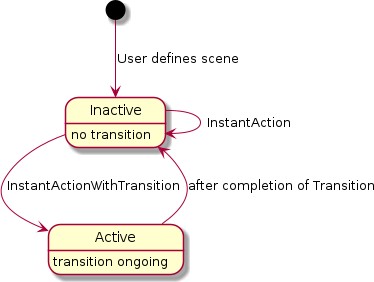
Figure 48. State diagram for example 'scene recall'
Example 2: Set dynamic light effect
User has defined a scene on a number of lights. The corresponding action would have these data fields describing it:
Name="sunset"
Type=scene
EndpointListID references a struct referencing the set of involved endpoints (same as in Example 1)
SupportedCommands: StartAction, StartActionWithDuration, StopAction
The StartActionWithDuration command (e.g. triggered by a voice command "play sunset in living room for 1 hour") will trigger the server to activate a dynamic pattern with colors inspired by sunset on the associated lights. At any time, the StopAction can be used to stop the effect.
Please note that the most of the data fields in the ActionStruct for this example are identical to those in example 1 - except for the SupportedCommands. The different sets of supported commands indicate whether it is an instant scene recall (example 1) vs. a long-term dynamic effort (example 2). A server could expose this action also as a single action with the combined set of supported commands.
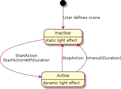
Figure 49. State diagram for example 'dynamic light effect'
Example 3: Pause sensor automation
User has defined an automation: a motion sensor controls the lights in a certain room. Sometimes, they want to override that automatic behavior, e.g. when having a party.
The action for this example would refer to such automation, which is typically active, but can be paused (=temporarily disabled).
The corresponding action would have these data fields describing it:
Name="motion sensor"
Type=automation
EndpointListID references a struct referencing the set of involved endpoints (same as in Example 1)
SupportedCommands: EnableAction, DisableAction, PauseAction, PauseActionWithDuration, ResumeAction
Typically, the action has been started when the user defines the motion sensor behavior, so without a Matter command the action’s state would be 'Active'. The PauseActionWithDuration command (e.g. triggered by a voice command "disable the motion sensor in living room for 2 hours") will trigger the server to disable the behavior associated with the motion sensor for the specified time.
A ResumeAction command would make this behavior active again. The automation could also have internal logic to abort the disabling after several hours or during the night-time reset, to accommodate for the case the user 'paused' and forgot to 'resume'.
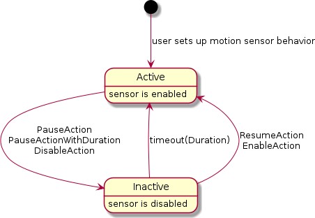
Figure 50. State diagram for example 'pause sensor automation'
Example 4: Wake-up routine
User has defined a wake-up routine: the lights in the bedroom will gradually become brighter and change in color temperature to simulate a sunrise. The sequence lasts for e.g. 30 minutes. Near the end of the sequence, the window coverings would be (partially) opened as well.
The corresponding action would have these data fields describing it:
Name="wakeup"
Type=sequence
EndpointListID references a struct referencing the set of involved endpoints (lights and window coverings in the bedroom)
SupportedCommands: EnableAction, DisableAction, DisableActionWithDuration, PauseAction, PauseActionWithDuration
When the user wants to snooze some more, he can use a voice command to trigger the PauseAction command (which could automatically timeout after e.g. 10 minutes). The StopAction command could similarly be used to cancel the remainder of the whole sequence. The DisableActionWithDuration (with parameter 172,800 =2*24*60*60 s) can be used on Friday evening to disable the sequence for the weekend.
When such action has been defined, a Matter node which is aware of the user’s calendar for the day, can use the StartAction command to trigger this sequence of events.
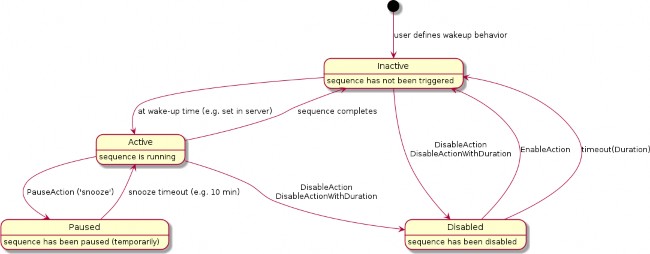
Figure 51. State diagram for example 'wake-up experience'
Example 5: Scheduled scene recall
User has setup a scene to be recalled at a certain time of day (e.g. colorful garden lighting to switch on around sunset) and switching off those lights (e.g. at midnight). The server’s automation system takes care of this. On certain occasions (e.g. garden party), the user wants to override this behavior (i.e. the scene should not be recalled at sunset because another scene has been set for the party).
The corresponding action would have these data fields describing it:
Name="colorful evening garden"
Type=automation
EndpointListID references a struct referencing the set of involved endpoints (lights in the garden)
SupportedCommands: EnableAction, DisableAction, DisableActionWithDuration
After installation, this action is in Inactive state. At the scheduled "on" time, the colorful garden lighting scene is activated and the action’s state changes to the Active state. At the scheduled "off" time, the lights are switched off, and the action’s state changes to the Inactive state. Using the DisableAction, the user can prevent these automated steps to occur - the action’s state changes to the Disabled state. Using the DisableActionWithDuration, the user can do similarly, but also indicate an automatic re-enabling after the specified time period. Using the EnableAction, the user can re- enable the automation.
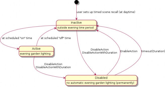
Figure 52. State diagram for example 'scheduled scene recall'
Example 6: Alarm system
User has an alarm system which exposes this cluster, with an action that allows to arm/disarm the system by voice commands from a Matter node which is a client to this cluster.
The corresponding action would have these data fields describing it:
Name="alarm system"
Type=automation
EndpointListID references a struct referencing the set of involved endpoints (elements of the alarm system)
SupportedCommands: EnableAction, DisableAction, DisableActionWithDuration
After installation, this action could be in Inactive state (assume user is at home installing so system is not armed). Using the EnableAction, the alarm system would be armed. Using the DisableAction, the alarm system would be disarmed (or disarmed for a period with DisableWithDuration).
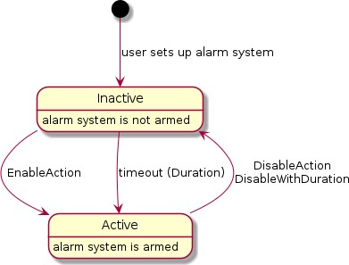
Figure 53. State diagram for example 'alarm system'
Proxy Architecture
Motivation
Constrained devices might not support more than a handful of subscriptions. This is usually attributable to a limited memory or battery. However, there might be a large number of clients who desire to subscribe to that device.
Subscription Proxy: Overview
A subscription proxy is a type of Node that is capable of multiplexing subscriptions from multiple subscribers onto a single subscription to a given publisher.
The term 'proxy' is a convenient shorthand that refers to this type of Node.
The term 'source' SHALL refer to a node that serves as the original source of truth for a set of data. The source acts as a publisher of that data.
The term 'client' SHALL refer to a node that wants to subscribe to some source.
A proxy subscribing to a source SHALL surface an identical 'mirror' of the source’s data to downstream clients without the clients having to alter their interaction regardless of whether they are interacting with a proxy or the source itself.
The proxy SHALL be identified by the Subscription Proxy Device Type.
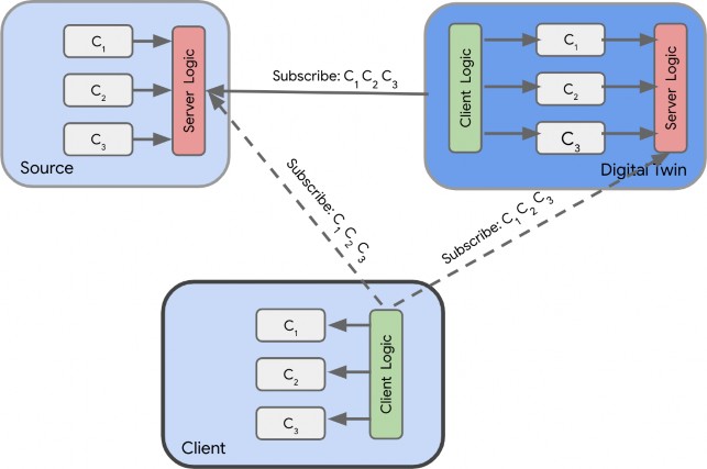
Figure 54. Digital twin acting as a proxy re-publishing clusters
This multiplexing of subscriptions allows the source to delegate all subscriptions to its proxy, only needing to support a single subscription from that proxy. This reduces the demands placed on energy and memory resources. Consequently, that single subscription will encompass the union of all client interest sets. If the combined set of attribute/event paths becomes fairly large, proxies can leverage the use of wildcards to merge multiple localized paths into a single, broader path with wildcards.
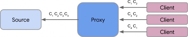
Figure 55. Proxy multiplexing interest sets from 3 distinct clients
A proxy SHALL only proxy subscribe interactions. It SHALL NOT proxy any other type of interaction.
Composition & Paths
A client subscribing to a proxy SHALL specify the Node ID of the source it wishes to subscribe to in the Path. This SHALL be different from the logical destination Node ID of the message, which
SHALL be the Node ID of the proxy.
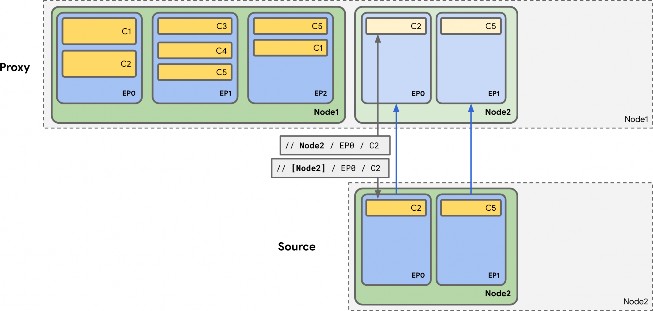
Figure 56. Sample paths when subscribing to a proxy vs the source
Proxy Subscriptions
Overview
A proxy only attempts to subscribe to a source when there is a current, valid subscription from a client to the proxy for that source’s data.
The term 'upstream subscription' refers to the subscription from the proxy either directly to the source, or indirectly to another proxy for that source’s data.
The term 'downstream subscription' refers to the subscription from either a client or another proxy to the proxy in question.
Consequently, when that 'downstream' subscription disappears, the 'upstream' subscription will either be torn down (if there are no other clients interested in that source) or be amended.
This does not require a priori knowledge of a client’s interest set.
Upstream/Downstream Subscription Mechanics
Upstream and downstream subscriptions have the following properties:
Both subscriptions are independent, but weakly linked.
Data is received on the client side, stored on the server side, and used to generate a different set of reports to downstream client(s).
It is data that is being proxied, not the actual subscription messages themselves.
The termination of a downstream subscription will automatically result in an amendment of the upstream subscription to remove the relevant paths that were in the downstream, with a
complete termination of the upstream subscription if there was only 1 downstream subscriber present.
The disappearance of an upstream subscription will not automatically cancel the downstream subscription.
Upstream subscriptions MAY disappear due to network connectivity issues. If an upstream sync report is not received, the proxy SHALL attempt once to re-subscribe to the upstream source; if that re-subscription attempt fails, the proxy SHALL terminate any associated downstream subscriptions.
If an upstream subscription is positively terminated by the source as a whole, that will result in a similar termination of the downstream subscription.
In addition to forwarding status codes embedded in the ReportData from the source, the proxy will convey a special 'NO_UPSTREAM_SUBSCRIPTION' IM status code to the downstream client if it has not established a subscription to the source.
The diagram below gives a sample sequence show-casing the two subscriptions:
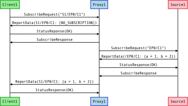
Figure 57. Upstream/Downstream subscription sequences
Sync/Liveness
Since subscriptions provide a 'sync' message to infer health of the subscription on both sides, it allows a client to monitor the health of its source peer.
Conveyance of this is preserved in downstream subscription through the 'NO_UPSTREAM_SUBSCRIPTION' status code. This conveys effectively the same information as the sync message would had the client directly subscribed to the source.
Upstream Subscription Parameter Derivation
Since the proxy multiplexes all downstream subscriptions onto a single upstream subscription, it has to have logic to harmonize the various parameters from each client subscription.
The following logic table describes what the proxy SHOULD do:
Parameter
Suggested Logic
Attribute/EventPaths
UNION of all paths. Proxy MAY use wildcards if needed to simplify this logic.
DataVersionList
MIN
EventNumberList
MIN
MinimumSyncInterval
MIN
MaximumSyncInterval
MAX
MinimumReportingIntervalList
MIN
ReportableChangeList
MIN
Since each client’s interest is different from the final multiplexed subscription, the proxy has to appropriately filter the data being received from the source before sending it to a given client.
Schemas and Data Serialization/Deserialization
Unlike clients that need to semantically interpret data in addition to deserializing/serializing to/from its internal data stores, a proxy only needs to do the latter.
As a result, proxies MAY achieve proxy functionality with a single firmware image built to handle any client, any cluster, any type of device.
Indirect Proxies
A proxy MAY subscribe to another proxy instead of subscribing directly to the source. This creates proxy chains that allow a single source to be proxied by multiple proxies, allowing better use of available proxy capacity.
Proxy Discovery & Assignment Flow
The following flow describes the process by which a client:
Discovers that a source needs a proxy
Finds an appropriate proxy on the network that is able to handle its request
Sets up the proxy to subscribe to the source
Step 0: Proxy Setup
A device indicates its ability to act as a certified proxy through stating support for the Subscription Proxy device type.
When such a device is commissioned, the commissioner SHALL recognize this ability and MAY write the NodeIds of all the sources that need proxying into the Proxy Configuration Cluster on the proxy device. Alternatively, it MAY configure the proxy to wildcard proxy all devices, removing the need to specify a particular set of NodeIds.
Additionally, the commissioner MAY write the Node ID of the newly added proxy to the Valid Proxies Cluster on source devices that needs proxying. This cluster stores the static list of candidate proxies for a given device. Only devices that support the cluster would need to have this configuration written.
Step 1: Rejection
There unfortunately isn’t any a priori heuristic that MAY be applied to deduce if a source needs proxying. This is usually a function of the number of clients subscribed to a source, the number of paths in those subscriptions, as well as the sync intervals.
When a source cannot handle any more incremental subscriptions, that is when proxying is needed. This is discovered when a client tries to subscribe to the source and is sent back a StatusResponse containing a RESOURCE_EXHAUSTED IM status code, indicating the source’s inability to handle further subscriptions:
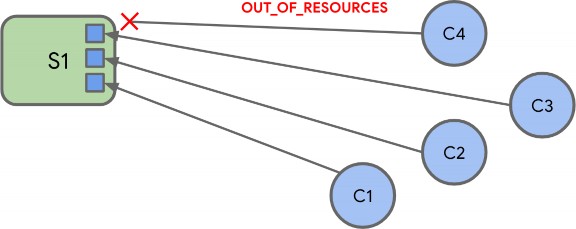
Figure 58. Rejection
In the diagram above, the constraints of the source have been simplified down to having 3 available subscription slots that get filled up.
Upon receipt of the RESOURCE_EXHAUSTED error, the client SHALL invoke the Get Valid Proxies Request command on the source Node. In response, it SHALL receive a Get Valid Proxies Response message containing the NodeIds of valid, candidate proxies.
Step 2: Proxy Discovery
After the client has received the list of possible valid proxies, the client MAY attempt to discover a valid proxy that is able to proxy its request.
To do so, the client sends out a Proxy Discover Request Command as a groupcast message to the All
Proxies universal group. Before it transmits this message, the client SHALL momentarily subscribe to the IPv6 address that maps to the All Proxies universal group to appropriately receive all responses.

Figure 59. Discovery Request
Step 3: Proxy Response
Proxies respond to the request with a Proxy Discover Response Command sent as a groupcast message to the All Proxies universal group. A proxy SHALL only send this message when it can handle the subscription request, regardless of whether it is currently subscribed to the source. The response will contain metadata about its ability to handle the subscription.
The Proxy Discover Response Command SHALL be sent as a completely separate, un-related transaction to the original request. The client SHALL correlate the two using the SourceNodeId present in both messages.
Proxies SHALL stagger their responses by waiting for a random interval between 0 and PROXY_SCAN_RESPONSE_JITTER before sending the Proxy Discover Response Command to prevent overwhelming the network or the client, which can be constrained and can have limited buffers.
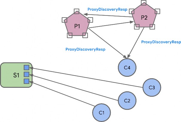
Figure 60. Proxies send back responses
Step 4: Proxy Selection
Client SHALL wait for PROXY_SCAN_PERIOD to aggregate all responses and SHALL filter the set of responses received. Specifically, the client SHALL discard:
Responses containing a Source Node ID for other unintended sources
Responses containing a Source Node ID in the message that does not match any in the ValidProxyList.
It SHALL then select a proxy from this filtered set based on implementation-chosen policies. One suggested approach would involve selecting the proxy with the least number of hops to the source, followed by largest available capacity.
Clients MAY unsubscribe from the IPv6 multicast group that maps to the All Proxies universal group after aggregating the responses.
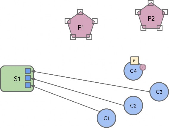
Figure 61. Selecting a Proxy
Step 5: Proxy Subscription
The client then subscribes to the proxy it has selected. The proxy will do one of two things:
Option 1: If there isn’t another proxy already subscribed to the source, the proxy subscribes to the
source directly:
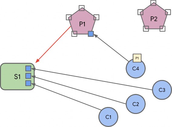
Figure 62. Primary proxy subscription
Option 2: If there is already another proxy subscribed to that source, the selected proxy subscribes to that proxy instead.
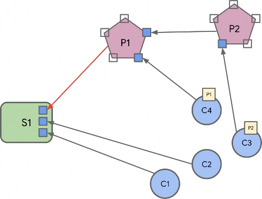
Figure 63. Primary proxy subscription
It doesn’t attempt to subscribe directly to the source since it does not know if the source has any free slots available to support the subscription, risking a potential subscription failure if it did so.
Proxies MAY select between the two options by 'sniffing' the `Proxy Discover Response Command messages that were emitted by other proxies. This allows the candidate proxy to determine whether there is another proxy already subscribed to the source.
A proxy SHALL have only one subscription to a given source regardless of the number of subscription requests from clients for that source. This is necessary to ensure timely ACL enforcement in the case where a client no longer has access to the source, and subsequent state changes will not be made available to that client (see ACL Enforcement for more details).
Step 6: Eviction
At this point, the source might not be able to handle another subscription. If so, it SHALL evict non- proxy subscriptions to make space for the proxy subscription. This is acceptable since those clients that got evicted MAY eventually subscribe to a proxy as well.
To make this possible, proxies have to express the type of subscription (proxy or not proxy) in the
SubscribeRequest itself.
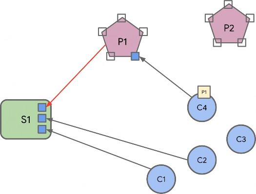
Figure 64. C3 gets evicted
Step 7: Re-Assignment
The evicted clients undergo the same proxy discovery/selection process, and eventually settle on a set of proxies.
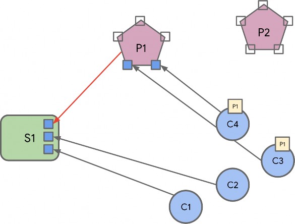
Figure 65. C3 gets reassigned to P1
Notable Characteristics
This algorithm has the following notable characteristics:
The system 'auto-balances' based on the needs of clients and the capabilities of the source
No persistent state or a priori configuration is needed on any node
No a priori heuristics are needed to figure out if a node should be proxied.
Robust to proxy failure by leveraging the liveness construct of subscriptions to accelerate discovery
No centralized proxy management/assignment service is needed.
There is no single point of failure. No need for an election, state backup, or fail-over.
Low complexity on server (which are usually the more constrained device), slightly more on the client
Constraints
Eviction Rules
A source SHALL NOT evict an existing proxy already subscribed to it to make way for a new subscription regardless of whether that new subscription emanates from a proxy or not. This prevents instability in the system since it might result in ping-ponging proxies subscribing to that source.
Number of Direct Proxies
There SHOULD only be one proxy node directly subscribed to a source in a single-fabric setting. This is not enforced by the source but rather, by proxies themselves.
Multi-Fabric
In a multi-fabric setting, a source node MAY be subscribed to by clients commissioned into different fabrics. It is highly desirable that a single proxy interacting with a source support clients from multiple fabrics. To make this possible, a proxy SHOULD when possible, be commissioned into all fabrics that contain sources that need proxying.
If a proxy is not commissioned into all fabrics, it might not see another proxy’s Proxy Discover Response Command messages, nor will it be capable of directly subscribing to that proxy even if it did, since it doesn’t have credentials to do so. This MAY result in multiple proxies attempting to subscribe directly to the source, resulting in potential rejection by the source and consequently, an inability for a client’s subscription to be served indirectly through that chosen proxy. This might be unpredictable depending on which proxy was able to subscribe first to that source.
Certification
To ensure a consistent expectation of behavior from a proxy device, the proxy SHOULD be certified by the Connectivity Standards Alliance against the expectations of a proxy. Once certified, it MAY claim compatibility against the Subscription Proxy device type.
Security & Privacy
Authentication
To prevent malicious or unattested devices from acting as proxies to clients, the Valid Proxies Cluster provides a scheme for admins to specify the NodeIds of valid, attested proxies to the source itself, which is in turn conveyed to clients. This allows for filtering of the ensuing Proxy Discover Response Command messages to only select valid, trusted proxies.
Multicast Messages
The proxy discovery commands SHALL be encrypted with a fabric-provided group key. An Administrator that wishes to enable proxy functionality on a set of clients SHALL bind the All Proxies group to a specific group key in the Group Key Management cluster.
Consequently, a Proxy Discover Request Command message SHALL be sent for every All Proxies
GroupID instance specified in the Group Keys Management cluster.
ACL Enforcement
Administrators SHOULD configure source nodes to grant the 'Proxy View' privilege to proxy clients. If this privilege is not granted for at least the Access Control cluster, the proxy will not function. This privilege SHOULD be granted for the entire source node for a proxy to be most effective, since neither the proxy nor the Administrator can predict which source clusters may be subscribed by other clients.
The proxy SHALL subscribe to the Access Control Cluster on the source and SHALL enforce the source’s ACLs on behalf of the source when serving its downstream client subscriptions.
The proxy MAY enforce the source’s ACLs eagerly (i.e. at first ACL change), lazily (i.e. at next data report), or by some combination of these approaches. The key guarantee is that the proxy SHALL apply the latest source ACLs from its upstream subscription at the time it generates associated downstream subscription reports.
The proxy SHALL enforce the source’s ACLs on a path by path basis, in a similar manner to how the Access Control Privilege Granting algorithm enforces access. Downstream subscription paths that are not granted access by the proxy SHALL cause the proxy to generate an UNSUPPORTED_ACCESS error for that subscription path.
If all report data paths in a downstream subscription result in UNSUPPORTED_ACCESS error, the proxy SHALL tear down that downstream subscription.
If the proxy is not able to view the source’s Access Control Cluster due to insufficient privileges, it SHALL NOT generate any downstream subscription data reports for that source. Instead, the proxy SHALL generate a report containing UNSUPPORTED_ACCESS errors for each path in the downstream subscription and tear down the downstream subscription.
Parameters and Constants
Table 83, “Glossary of constants” is a glossary of constants used in this section, along with a brief description and example default for each constant.
Table 83. Glossary of constants
Constant Name
Description
Default Value
PROXY_SCAN_RESPONSE_JITTER
The maximum amount of time to randomly wait before sending a Proxy Discover Response Command message.
1000
milliseconds
PROXY_SCAN_PERIOD
The maximum amount of time initiator of proxy discovery will wait to collect Proxy Discover Response Command messages after sending a Proxy Discover Request Command message.
1100
milliseconds
Clusters
Proxy Discovery Cluster
This cluster contains commands needed to do proxy discovery as defined in the Section 9.15.7.3, “Step 2: Proxy Discovery” and Section 9.15.7.4, “Step 3: Proxy Response” steps of the overall Section 9.15.7, “Proxy Discovery & Assignment Flow”.
Revision History
The global ClusterRevision attribute value SHALL be the highest revision number in the table
below.
Rev isio n
Description
1
Initial Release
Classification
Hierarchy
Role
Context
PICS Code
Base
Utility
Node
PXDSC
Cluster Identifiers
Ident ifier
Name
0x004
3
ProxyDiscovery
Server Attributes
None
Commands
Id
Name
Direction
Response
Access
Conformance
0x00
Proxy Discover Request
Client ⇒ Server
N
O
M
0x01
Proxy Discover Response
Server ⇒ Client
N
M
Proxy Discover Request Command
This command is used during proxy discovery, as specified in Section 9.15.7, “Proxy Discovery & Assignment Flow”.
Id
Field
Type
Constraint
Quality
Default
Conforman ce
0
SourceNode Id
node-id
all
M
1
NumAttribu tePaths
uint16
desc
M
2
NumEventP aths
uint16
desc
M
SourceNodeId
This is the Node ID of the source for which a client seeks to find a Proxy.
NumAttributePaths
The number of attribute paths the client will have in the subscription request. This is a heuristic/hint to allow a Proxy to better ascertain whether it can support the ensuing subscription.
NumEventPaths
The number of event paths the client will have in the subscription request. This is a heuristic/hint to allow a Proxy to better ascertain whether it can support the ensuing subscription.
Proxy Discover Response Command
This command is used during proxy discovery, as specified in Section 9.15.7, “Proxy Discovery & Assignment Flow”.
Id
Field
Type
Constraint
Quality
Default
Conforman ce
0
SourceNode Id
node-id
all
M
1
NumHopsT oSource
uint16
desc
M
2
AvailableCa pacity
uint16
desc
M
SourceNodeId
This is the Node ID of the source the proxy can proxy for. This SHALL match the node id in the corresponding Proxy Discover Request Command message.
NumHopsToSource
If the proxy currently subscribes to the source (either directly or indirectly), this indicates the number of hops to the source. Sensible values start at 1, with 1 being used for a proxy that subscribes directly to the source. If the proxy is not subscribed directly to the source, this value SHALL be one greater than the NumHopsToSource for the given Node ID of the proxy it is subscribed to.
0 indicates that the proxy currently does not have a subscription to the source.
AvailableCapacity
A number indicating the number of Cluster Attribute Paths the proxy has space for support. This allows for an absolute comparison of different memory capacities of candidate proxies by the client in selecting the best possible candidate.
Proxy Configuration Cluster
This cluster provides a means for a proxy-capable device to be told the set of Nodes it SHALL proxy.
Revision History
The global ClusterRevision attribute value SHALL be the highest revision number in the table below.
Rev isio n
Description
1
Initial Release
Classification
Hierarchy
Role
Context
PICS Code
Base
Utility
Node
PXCFG
Cluster Identifiers
Ident ifier
Name
0x004
2
ProxyConfiguration
Definitions
9.15.14.4.1. ConfigurationStruct
Quality: Fabric-Scoped
Id
Name
Type
Constraint
Quality
Access
Default
Conforma nce
1
ProxyAllN odes
bool
desc
RW
false
M
2
SourceList
list[node- id]
desc
RW
empty
M
ProxyAllNodes
This field SHALL be set to to 'true' to indicate to the proxy that it SHALL proxy all nodes. When 'true', the SourceList attribute is ignored.
SourceList
When ProxyAllNodes is 'false', this list contains the set of NodeIds of sources that this proxy SHALL specifically proxy.
Server Attributes
Table 84. Cluster Server Attributes
Id
Name
Type
Range
Quality
Access
Default
Conforma nce
0
Configura tionList
list[Config urationStr uct]
all
N
RW
empty
M
9.15.14.5.1. ConfigurationList
List of proxy configurations. There SHALL NOT be multiple entries in this list for the same fabric.
Valid Proxies Cluster